ALINTE
4
PAGE
I
NSTALLATION
G
UIDE
4-21
4.4.2 Mate the Autoloader and Engine
The autoloader and engine are mated as follows:
1.
Move the autoloader close to the engine and route the following
cables between the two units:
1.
V6A_ILOCK
: from the autoloader interlock switch to the free end
of V6_ILOCK (after detaching the shorting connector - if fitted).
WARNING: make sure this cable is fitted to ensure full operator safety
when the auoloader top cover is removed.
2.
V6A_CAN_AUTO
: from MSB3 SK1 to MSB2 SK3. This cable is in
the Accessories pack.
3.
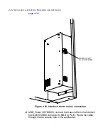
V6A_MSB3_PWR
: from MSB3 PL31 to MSB3_PWR connector on
the Interlock box. Route this cable back to the Interlock box on the
engine and secure.
4.
Check that LK1 and 2 are not fitted on MSB2 and fitted on MSB3,
see
Figure 4.17 on page 4-21
.
Figure 4.17 Location of LK1 and 2 on MSB2
2.
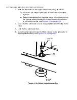
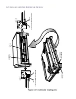
Obtain the 4-off seating plates (anchor feet) from the accessories
pack and locate them underneath each autoloader jack bolt, see
Figure 4.18 on page 4-22
.
LK1
LK2
Summary of Contents for alinte4page
Page 1: ......
Page 12: ...PRELIMINARIES...
Page 29: ...ALINTE4PAGE INSTALLATION GUIDE 2 7 Figure 2 5 Autofeeder elevator warning label...
Page 40: ...2 18 SAFETY ON THE ALINTE4PAGE Figure 2 13 Location of interlock covers alinte4page SAL 2 1...
Page 48: ...2 26 SAFETY ON THE ALINTE4PAGE...
Page 56: ...3 8 UNPACKING AND HANDLING...
Page 98: ...4 42 INSTALLING ALINTE4PAGE EQUIPMENT AND SOFTWARE Figure 4 32 Removing transit fixing view 2...

