Disk
Ø 4,3
Front axle
carrier left
Screw
4x14
Screw
4x14
Screw
4x14
Alloy battery
fixing brace F1
Drill the alloy battery
fixing brace F1 to
7mm if using the 3rd
receiver fixing.
Alloy
chassis
Screw
2,9x13
Receiver
battery
Body mount
Body clip
Dampening
rubber
Battery/
body bolt
Screw
2,9x9,5
Screw
2,9x19
Screw
2,9x16
Receiver box
Flexible aerial
Mount for flexible aerial
Stop
nut M4
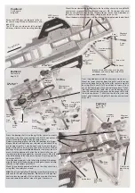
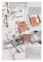
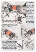
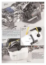
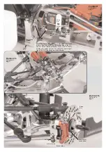
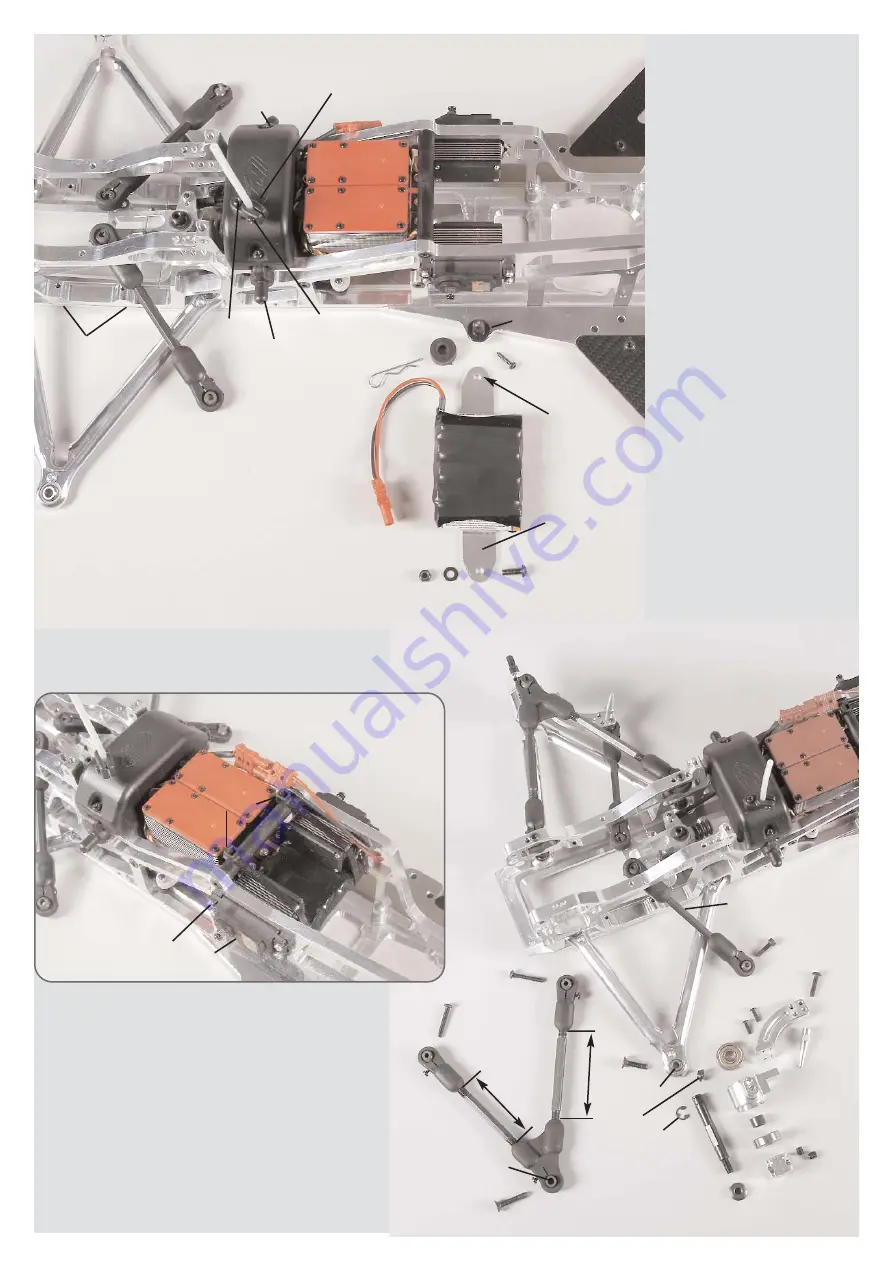
Mount the left front axle carrier to the
alloy chassis and the alloy front chas-
sis using M4x14 countersunk screws .
Mount the servo mounting brace to the
left front axle carrier using 4.2x16
countersunk screws. Mount the dis-
tance bolt to the left front axle carrier
using a 4.2x19 countersunk screw.
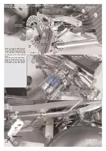
Mount the throttle-brake servo and the
brake servo to the front axle carrier
using M2.5x12 pan-head screws.
Drill out the aerial hole by 3mm at the
lid of the receiver box and mount the
aerial mount to the lid of the receiver
box using a 2.9x19 pan-head screw.
Insert the flexible aerial through the fle-
xible aerial mount and clamp it with a
2.9x9.5 pan-head screw.
In order to lead-in the servo cables, cut
out a hole of a diameter of approx.
10mm at an appropriate position bet-
ween the lower and upper part of the
box.
Put the lower part of the box on the
body mounts. Connect all servo ca-
bles and battery cables to the receiver
and check if it is working properly. Le-
ad-in the aerial cable through the ho-
le of the upper part of the box and
through the flexible aerial. Now stow
the cable remnants of the servos in the
receiver box, mount the lower and up-
per part of the receiver box to the bo-
dy mounts using the 2.9x16 pan-head
screws.
Hint:
Cover the lower part of the re-
ceiver box with some foam in order to
protect the receiver against vibrations.
Position 16
Parts are in
bag I
Position 17
Parts are in
bag G+H
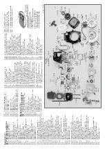
Track rod
mounted
Alloy
steering
stop
Wheel nut M6
a
p
p
ro
x
. 7
1
m
m
appr
ox. 62mm
Retaining
washer Ø 5
Driving
axle
Square
wheel
14mm
Alloy
steering
arm
Bevel
disk
Left alloy
uprights axi-
ally displaced
Distance
bush
Ball bearing
8x22x7
Front upper
wishbone
left mounted
Screw
5x25
Screw
3x10
Screw
4x14
Screw
4x18
Screw
5x20
Screw
2,9x13
Screw
4x25
Screw
4x25
Headless
pin 6x6
Front axle
carrier left
Ball
bush
Position 16a
Parts are in
bag I
Brake servo
Brake servo
Cable clip
Receiver
battery
Throttle-
brake servo
Throttle-
Brake servo
Screw
2,5x12
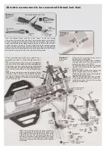
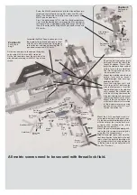
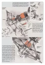
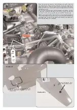
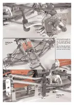
Push the securing disk in the 2nd groove of the driving axles, then in-
sert it in the alloy uprights equipped with ball bearings according to
the illustration position 17. Then, mount the square wheel driver 14mm
with recess facing the bearing on the flat side of the driving axle by
using M6x6 headless pins. Mount the alloy steering arm to the alloy
uprights using M3x10 pan-head screws. Mount the alloy uprights using
M5x20 countersunk screws and bevel disk (thin side facing the ball-ty-
pe nipple) between the alloy upright and the front lower alloy wishbo-
ne. Mount the pre-assembled upper wishbones to the front axle car-
riers using M4x25 pan-head screws. Mount the upper wishbones to
the outside of the alloy uprights using M5x25 countersunk screws. Fix
the alloy steering stops to the alloy steering arms (front outer thread bo-
ring) by using M4x18 pan-head screws. Mount the track rods to the al-
loy steering arms (rear inner thread boring) using M4x14 cylinder screws.
Hint:
Pay attention to the mounting direction of the upper wishbones,
mount the shorter side facing the front. The front alloy uprights are axi-
ally displaced, mount the side with the two threaded holes facing the
top.
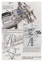
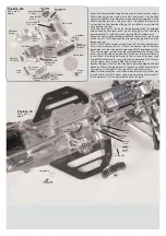
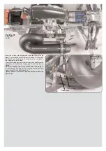
There are 3 possibilities to fasten the receiver battery:
1. Fix the receiver battery from the bottom to the throttle-brake servo
and brake servo using cable clips as illustrated in position 16a.
2. Fix the receiver battery with adhesive tape centred on the alloy bat-
tery fixing brace F1. Now mount the alloy battery fixing brace F1 under
the throttle/brake servo and brake servo on both sides of the alloy chas-
sis by using M4x14 pan-head screws, disks Ø 4,3 and M4 stop nuts.
3. Drill the fixing holes of the alloy battery fixing brace F1 on both sides
to 7mm and fix the receiver battery with adhesive tape centred on the
F1 fixing brace. Mount the battery/body bolts on both sides of the al-
loy chassis using 2,9x13 pan-head screws. Fix the alloy battery fixing
brace F1 on the battery/body bolts under the throttle/brake servo and
brake servo with dampening rubber and body clip.
Hint:
The 3rd mounting version of the receiver battery enables a quick
changing of the receiver battery.


