Farmer-Helper 25 & 27G
7
Revision06/2017
SECTION 2: OPERATION
Understanding Spreader Operation
Proper and safe operation of the F a r m e r H e l p e r 27G Spreader requires: (1) being familiar with the
spreader's
operating components and (2) heeding all safety precautions as stated in this manual.
The Spreader Operating Components
By definition, the left and right sides of the spreader are determined while sitting on the tractor seat.
The following operating components are included with all Model
21+131+
spreaders:
The left hand sp re ad e r lever
engages thefloor apron chain which moves the manure to the
rear o f the spreader and into the beater.
The right hand sp read er lever
engages the chain that drives the beater and spreads the
manure.
The following are optional operating components included with some Model
21+131+
spreaders (depending on
the specific model configuration ordered):
The jack stand dolly wheel option allows easy movement of the spreader around the stable
or bam; also adjusts the height of the spreader to facilitate hook-up to the spreader towing vehicle.
The end gate helps to contain loads between spreading and also shields the operator during
spreading.
Connecting the Spreader to the Towing Vehicle
For operation in the field, the F a r m e r H e l p e r M odel
27G
spreaders can be towed by a num ber of vehicles--
garden tractor, A TV , or utility vehicle. Please adhere to the following procedure for connecting the spreader to
your towing vehicle.
Attaching the spreader to the towing vehicle as instructed is necessary for safe
and proper operation of the equipment.
1.
Back the towing vehicle within a few inches o f the spreader hitch.
2.
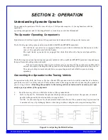
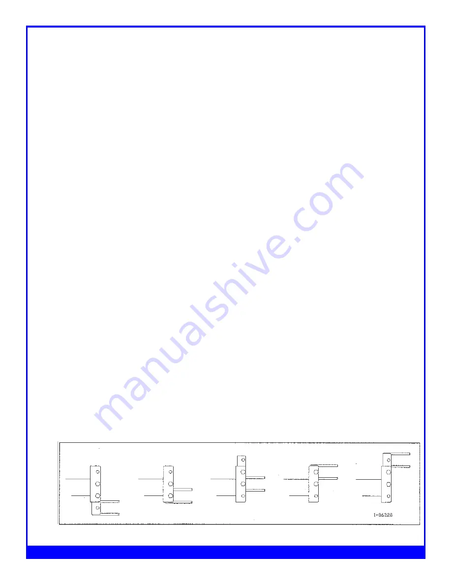
Refer to Figure 2A. Determine the spreader hitch position required to allow the spreader to remain
parallel to the ground with relation to the towing vehicle.
N O TE: As shown in Figure 2A, the adjustable hitch on the front of the spreader may be positioned in
A number of ways, by sliding up/down or inverting, to achieve a higher or lower positioning of the
Figure 2A - Adjusting the Hitch Position
Summary of Contents for FH-25G
Page 6: ...Farmer Helper 25 27G 6 Revision06 2017...
Page 18: ...Exploded View of 25G Manure Spreader Farmer Helper 25G 18...
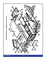
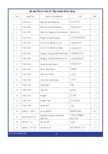
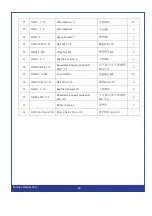
Page 20: ...Exploded View of Spreader Box Farmer Helper 25G 20...
Page 23: ...Exploded View of Transmission Assy Farmer Helper 25G 23...
Page 26: ...Exploded View of Tire Assy Farmer Helper 25G 26...
Page 28: ...Exploded View of Widespread Shaft Assy Farmer Helper 25G 28...
Page 30: ...Exploded View of Chain Tension Assy Farmer Helper 25G 30...
Page 32: ...Exploded View of Hitch Assy Farmer Helper 25G 32...


