background image

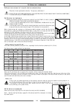
Read all the information provided in Section 7.1 before proceeding with any maintenance jobs.

c

HangIng


tHe


oIl

Change the oil following the initial 500 hours of use and then every 

2500 hours and in event once a year. 

In case of not frequently use (few hours of duty per day) you should 

change the oil every 6 months.

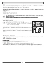
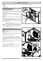
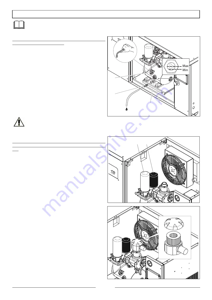
When you open the knurled fitting 2, oil starts to drain from the 

screw unit, therefore you need to have a pipe and container ready 

to collect the oil

Unscrew the cap 1 situated at the base of the screw unit.

Screw an attachment with tail piece 2 (supplied together with the 

compressor).

Open tap 3.

Once emptied, shut-off tap 3 and remove the attachment with tail 

piece.

Fill-up with oil to the half of the union 4, then screw cap 1 back in 

place and close-up the compressor again.

Once the oil and oil filter have been changed leave the compressor 

to run for roughly 5 minutes then turn it off and check the oil level 

again. Add oil if necessary.

Check the oil level once a month.

Never mix different types of oil,

 therefore always 

ensure that the circuit is completely empty before fil-

ling-up with oil.  Each time the oil is changed the filter 

is also to be replaced

r

eplacIng


tHe


oIl


FIlter


cartrIdge

Replace the oil filter cartridge after the first 500 hours of use then 

every 2500/3000 hours and in any event each time the oil is chan-

ged.

Open the rear panel.

Disassemble filter cartridge A, using a chain spanner and replace 

with a new one.

Lubricate  the  sealing  gasket  before  screwing  the  filter  cartridge 

tight.

Manually tighten the new filter cartridge.

r

eplacIng


tHe


FIlter


cartrIdge


oF


tHe


oIl


separator

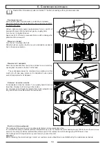
Open the side panel to gain access to inside the compressor.

Disassemble filter cartridge B, using a chain spanner and replace 

with a new one.

Lubricate  the  sealing  gasket  before  screwing  the  filter  cartridge 

tight.

Manually tighten the new filter cartridge.

r

eplacIng


tHe


aIr


FIlter


cartrIdge

Open the side panel to gain access to inside the compressor.

Remove the cover.
Replace the cartridge of the air filter and replace the cover.

1

2

3

4

A

B

17

6 . c

ompressor


maIntenance

Summary of Contents for New Silver Series

Page 1: ...ing the appropriate safety standards The fundamental safety standards are listed in the SAFETY section of this manual and also in the section involving the use and maintenance of the compressor Hazardous situations to be avoided in order to prevent serious personal injuries and machine damages are listed in the WARNINGS section of the instruction manual or are actually printed on the machine Never...

Page 2: ...4 Installation 9 4 1Admitted surrounding conditions 9 4 2Space required for maintenance 9 4 3Positioning the compressor 10 4 4Connecting the compressor and relative inspections 10 5 Using the compressor 12 5 1Preparing to use the compressor 12 5 2Controls indicators and safety devices 13 5 3 Check the efficiency of the safety devices before starting 15 5 4Starting the compressor 15 5 5Stopping the...

Page 3: ...e Consulting the manual This instruction manual is made up of the following FRONT COVER WITH MACHINE IDENTIFICATION DETAILED INDEX INSTRUCTIONS AND OR NOTES ON THE COMPRESSOR The model and serial number of the compressor to which the manual refers and that you have purchased is found on the FRONT COVER The various SECTIONS in which all the notes relative to a certain subject are found in the INDEX...

Page 4: ...y touching the metal parts of the compressor with your body such as pipes the tank or metal parts connected to earth Never use the compressor where there is water or in damp rooms 5 DISCONNECT THE COMPRESSOR Disconnect the compressor from the electric power supply and completely discharge the pressure from the tank before carrying out any service inspection maintenance cleaning replacing or inspec...

Page 5: ...as oil or other compounds that contain hydrocarbons may damage the plastic parts Clean them with a soft cloth and soapy water or other suitable liquids 23 USE ORGINAL SPARE PARTS ONLY The use of non original spare parts involves the annulment of the guarantee and the abnormal running conditions of the compressor Original spare parts are available c o the authorised dealers 24 DO NOT MODIFY THE COM...

Page 6: ...reater than 200 C NEVER MIX DIFFERENT OIL QUALITIES Suggested oil Screw oil SYNT D46 Use oil with VG32 rating for cold climates and VG68 for tropical climates It is advisable to use synthetic oils for very hot and humid climates 2 2 Intended use The silent rotary screw compressors have been designed and manufactured exclusively to produce compressed air EVERY OTHER USE DIFFERENT AND NOT FORESEEN B...

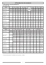
Page 7: ... 45 5 45 5 45 5 45 5 45 5 45 5 45 5 45 Noise level dB A 63 63 63 64 64 64 65 65 65 66 66 66 Model HP 10 10 S kW 7 5 HP15 kW 11 HP 20 kW 15 Max Pressure Bar 8 10 13 8 10 13 8 10 13 psi 116 145 188 116 145 188 116 145 188 Free air delivery ISO 1217 l min 950 10 860 10 690 10 1560 1430 1210 2010 1900 1670 1180 10 S 1010 10 S 800 10 S cfm 33 10 30 2 10 24 2 10 55 50 4 42 7 70 9 67 58 9 41 10 S 35 6 10...

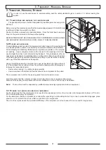
Page 8: ...e damaged parts if possible and forward everything to your insurance company with copy to the Manufacturer and transporter Using a forklift truck take the compressor as near as possible to the place where it is to be installed then carefully remove the protective packing without damaging it following the instructions below Remove the packing 1 by sliding it away upwards Unscrew screws 2 that block...

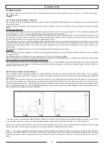
Page 9: ... EXPLOSION AND OR FIRE The standard compressor is not pre arranged or designed to work in rooms subject to the risk of explosion or fire The performance of the compressor may decrease at the maximum permitted ambient temperature with relative humidity higher than 80 and at an altitude of more than 1 000 mt 4 2 Space required for maintenance The compressor must be installed in a large room that is ...

Page 10: ...nnection Never use damaged or squashed extension cables Ensure that the extension cable is in a good state of wear When using an extension cable ensure that the cross section of the cable is sufficient to convey the current absorbed by the product to be connected If the extension cable is too thin there could be drops in voltage and therefore loss in power and overheating of the equipment The exte...

Page 11: ...trical power supply cables relative to the three phases that causes the incorrect rotation direction of the screw unit In this event compressor stops Invert a wires of the terminal board and connect to the main supply Start compressor and visually check the rotation direction as shown by the arrow on the back side Warning The incorrect rotation direction for more than 20 seconds will irreparably d...

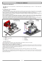
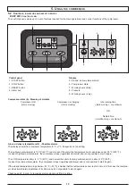
Page 12: ...ny abnormal conditions The temperature of the air oil mix at the screw outlet is controlled by a thermostatic probe which stops the compressor if the temperature is too high 1 Oil filter 2 Minimum pressure valve 3 Air end 4 Electric motor 5 Transmission belt 6 Air filter 7 Oil radiator 8 Oil separator Functions descriptions When the compressor is connected to power supply display shows initial scr...

Page 13: ...erature in C or F it depends on the setting The high temperature alarm is 105 C 221 F and to reset the alarm the temperature has to decrease under 95 C 203 F In case of high temperature alarm the compressor stops regardless its status and is not possible to start it again The LOW temperature alarm is 5 C 23 F and to reset the alarm the temperature has to be above 10 C 50 F In case of low temperatu...

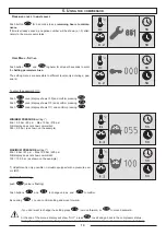
Page 14: ...Max 15 bar 218 psi N B display does not show comma dot 055 5 5 bar as shown on the example MAXIMUM PRESSURE setting Min 6 bar 87 psi Max 15 5 bar 225 psi N B display does not show comma dot 100 10 0 bar as shown on the example Adjustment is only possible on models equipped with a pressure sen sor BP TO MODIFY setting push value is flashing Push buttons and to change values and to confirm By pushin...

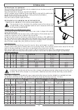
Page 15: ... compared to maximum pressure Shut off the air outlet tap and wait for the pressure transducer to trip which will shut on the in take valve and close the internal discharge Setting made by the manufacturer The minimum setting pressure is 6 8 and 11 bar dependign from the maximum pressure 8 10 or 13 bar The thermal relay is set according to the table below HP kW V220 240 50 60Hz V380 415 50 60Hz di...

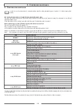
Page 16: ...500 hours after first start Change oil Check the electrical connections and tighten if necessary every 2500 hourso once a year Replace the oil filter cartridge Replace the filter cartridge of the oil separator Replace the air filter cartridge Check the transmission Clean the air oil radiator Check filters in electrical cabinet and replace if necessary Clean inverter dissipator if equipped Check th...

Page 17: ...f necessary Check the oil level once a month Never mix different types of oil therefore always ensure that the circuit is completely empty before fil ling up with oil Each time the oil is changed the filter is also to be replaced Replacing the oil filter cartridge Replace the oil filter cartridge after the first 500 hours of use then every 2500 3000 hours and in any event each time the oil is chan...

Page 18: ...rained is considered as polluting mix that must not be thrown away outdoors It is advisable to use special water oil separators for its disposal Cleaning the air oil radiator It is advisable to clean the radiator 1 on a weekly basis to remove impurities blowing it with an air gun from inside low compressed air through the radiator from inside outwards ma king sure that no dirt settles inside the c...

Page 19: ...isconnected Compressor does not star or stops Press to reset Alarm can be reset only once the problem is solved To be ignored for version with pressure switch Alarm MAINTENANCE TIME ESPIRED Compressor keep on working Alarm can be reset only after maintenance is done Contact your local after sale service 6 2 Diagnosing the alarm status inconveniences faults Before doing any job on the compressor en...

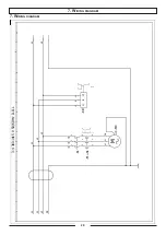
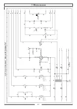
Page 20: ...7 Wiring diagram 20 7 Wiring diagram ...

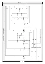
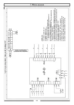
Page 21: ... 21 7 Wiring diagram ...

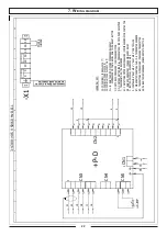
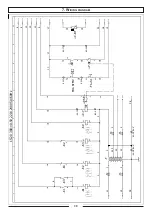
Page 22: ... 22 7 Wiring diagram ...

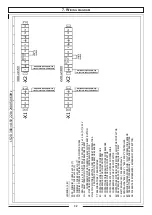
Page 23: ... 23 7 Wiring diagram ...

Page 24: ... 24 7 Wiring diagram ...

Page 25: ... 25 7 Wiring diagram ...

Page 26: ... 26 7 Wiring diagram ...

Page 27: ... 27 7 Wiring diagram ...

Page 28: ... 28 7 Wiring diagram ...

Page 29: ... 29 7 Wiring diagram ...

Page 30: ... 30 7 Wiring diagram ...

Page 31: ... 31 7 Wiring diagram ...

Page 32: ... 32 7 Wiring diagram ...

Page 33: ... 33 7 Wiring diagram ...

Page 34: ... 34 7 Wiring diagram ...

Page 35: ... 35 7 Wiring diagram ...

Page 36: ... 36 7 Wiring diagram ...

Page 37: ...37 7 Wiring diagram 7 Wiring diagram ...

Page 38: ...38 7 Wiring diagram ...

Page 39: ...39 7 Wiring diagram ...

Page 40: ...40 7 Wiring diagram ...

Page 41: ...41 7 Wiring diagram ...

Page 42: ...42 7 Wiring diagram ...

Page 43: ...43 7 Wiring diagram ...

Page 44: ...44 7 Wiring diagram ...

Page 45: ...45 7 Wiring diagram ...

Page 46: ...46 7 Wiring diagram ...

Page 47: ...47 7 Wiring diagram ...

Page 48: ...48 7 Wiring diagram ...

Page 49: ...49 7 Wiring diagram ...

Page 50: ...50 7 Wiring diagram ...

Page 51: ...51 7 Wiring diagram ...

Page 52: ...52 7 Wiring diagram ...

Page 53: ...53 7 Wiring diagram ...

Page 54: ...54 7 Wiring diagram ...

Page 55: ...55 7 Wiring diagram ...

Page 56: ...56 7 Wiring diagram ...

Page 57: ...Diagram 1 Intake filter 2 Intake valve 3 Air end 4 Oil separator tank 5 Oil separator filter 6 Minimum pressure valve 7 Radiator 8 Oil filter 9 Safety valve 1 2 3 8 7 4 6 5 9 AIR OIL AIR OIL 57 8 Pneumatic Diagram ...

Page 58: ...Model Serial No Date Intervention Working hours Signature 9 Maintence Schedule 58 9 Maintence Schedule ...

Page 59: ...59 9 Maintence Schedule ...

Page 60: ...Cod 1127340124_02 2017 ...

Reviews: