background image

40

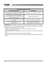
A long press (> 4 seconds) of the reverse button enters “Smart Pro” programming of 

some functional parameters.  Press the lever the number of times indicated beside the 

desired function.  Press the reverse button again to exit from programming mode.

Lever presses 

Function 

Description

FUNCTION CONFIGURATIONS

The tool turns for as long as pressure is kept on the lever
The tool turns keeping while pressure is kept on the PTS
The tool turns (Lever Start + Push-to-start) while si-

multaneously keeping pressure on the lever and on 

the PTS; releasing the PTS will trigger an error)
The tool starts/stops when the lever is RELEASED and with the 

Push-to-start maintained. (It is not necessary to keep pressure 

on the lever; releasing the Push-to-start will trigger an error)

Function managed in the TPU M1 monitoring unit

Enables/disables the light over the work area while 

the screwdriver is rotating. Resets the front flashing 

light when 1,000,000 cycles have been reached

Enables/disables untightening

Screwdriver will gradually reach 100% of set speed 

in 1,5 sec.

Of 4 turns (keep combination of start during all the 

cycle, pause included).

Of 4 laps (keep combination of start during all the 

cycle, pause included).

Lever start (default)

Push-to-start (PTS)

Lever start + Push-to-start 

“Latched lever” + push 

to start

Lock in case of error,   

ON/OFF (default OFF)

Front light

(default ON)

Enable untightening

(default ON)

SLOW START

PRE-AUTO

UNTIGHTNEING

POST-AUTO

UNTIGHTENING

1

  2*

  3*

  4*

5

6

7

8

9

10

OPERATING OPTIONS

Summary of Contents for eTensil E8C1A-1200

Page 1: ...anica e arresto automatico e unità di alimentazione Electric solutions with mechanical clutch and automatic shut off and power supply Solutions électriques avec embrayage mécanique et arrêt automatique et unitées d alimentation Soluciones électricas para atornillar con embrague mecánico y unidades d alimentación Elektrische Lösungen mit mechanischer Kupplung mit automatischer Abschaltung und die S...

Page 2: ......

Page 3: ...A30 650 E8C5A30 350 motori per avvitare elettrici E8MC1A 1200 E8MC1A 900 E8MC1A 650 E8MC2A 2000 E8MC3A 1200 E8MC3A 900 E8MC4A 650 E8MC5A 350 Noi FIAM Utensili Pneumatici S p A Vicenza Italia dichiariamo sotto la nostra esclusiva responsabilità che il prodotto al quale questa dichiarazione si riferisce è conforme a quanto previsto dalle direttive Direttiva Macchine 2006 42 CE Direttiva Compatibilit...

Page 4: ...RE PER AVVITARE 15 OPZIONI DI FUNZIONAMENTO 16 IMPUGNATURA DELL UTENSILE E MONTAGGIO SU BRACCIO DI REAZIONE 17 STAFFAGGIO DEL MOTORE PER AVVITARE 18 MODELLI ALIMENTATORE 19 DESCRIZIONE DELL ALIMENTATORE 19 INFORMAZIONI LED ALIMENTATORE 20 INFORMAZIONI PULSANTE IMPOSTAZIONE VELOCITÀ 20 CONNETTORE INGRESSI USCITE SOLO PER MODELLO TPU 2 21 CARATTERISTICHE TECNICHE DELL ALIMENTATORE 22 MANUTENZIONE DE...

Page 5: ...IO DI PERICOLO L operatore deve consultare il presente manuale ogni volta che vedrà questo simbolo di pericolo OBBLIGO LETTURA DEL MANUALE Leggere il manuale di istruzioni prima di utilizzare il prodotto EPA L avvitatore è conforme alla norma IEC 61340 5 1 È quindi possibile utilizzarlo all interno delle aree EPA Electrostatic Protected Area MARCHIO CE Il prodotto è conforme alle direttive europee...

Page 6: ...con utensili elet trici dotati di messa a terra a massa Spine non modificate e prese corrispon denti riducono il rischio di scossa elettrica b Evitare il contatto del corpo con superfici collegate a terra o a massa quali tubi radiatori cucine e frigoriferi Se il vostro corpo è a terra o a massa il rischio di scossa elettrica aumenta c Non esporre gli utensili elettrici alla pioggia né utilizzarli ...

Page 7: ...n situazioni impreviste f Vestirsi in modo appropriato Non indossare vestiti larghi né gioielli Tenere capelli indumenti e guanti distanti dalle parti in movimento Vestiti larghi gio ielli o capelli lunghi possono impigliarsi nelle parti in movimento g Se vi sono dispositivi da collegare a impianti per l estrazione e la raccolta di polvere accertarsi che siano collegati e usati in maniera appropri...

Page 8: ...pericolose h Mantenere l impugnatura e le altre superfici di presa asciutte e pulite da oli e grassi Le impugnature scivolose non garantiscono una presa sicura e il control lo dell utensile nelle situazioni impreviste 5 Assistenza a Far riparare l utensile elettrico solo da tecnici qualificati e utilizzare solamente ricambi identici Ciò garantisce la costante sicurezza dell utensile elettrico 6 Al...

Page 9: ... 590 870 435 640 320 340 170 0 6 0 6 0 6 0 6 0 6 2 5 3 0 3 5 4 0 4 5 E8C2A30 2000 E8C3A30 1200 E8C3A30 900 E8C4A30 650 E8C5A30 350 111712035 111712036 111712037 111712038 111712039 MODELLI ANGOLARI 90 MODELLI DIRITTI MODELLI ANGOLARI 30 1180 590 870 435 640 320 2000 1000 1180 590 870 435 640 320 340 170 0 3 0 3 0 3 0 6 0 6 0 6 0 6 0 6 1 6 1 6 1 6 2 5 3 0 3 5 4 0 4 5 E8C1ARE 1200 E8C1ARE 900 E8C1AR...

Page 10: ...tensile fornito in dotazione prima al con nettore circolare dell utensile successivamente collegare l altra estremità del cavo al connettore circolare presente sul frontalino dell alimentatore 2 Collegare il cavo di alimentazione dell alimentatore alla presa posta sul retro dell a limentatore Successivamente collegare il prodotto alla rete di alimentazione e accenderlo Fiam consiglia di utilizzare...

Page 11: ...LED n 2 spento Rotazione destra oraria LED n 1 acceso LED n 2 acceso Per passare da rotazione destra a sinistra e viceversa premere e rilasciare veloce mente il pulsante inversione senso di rotazione Si rimanda al paragrafo OPZIONI DI FUNZIONAMENTO per le altre funzionalità del pulsante inversione senso di rotazione LED n 1 LED n 2 Pulsante inversione senso di rotazione Leva di avviamento ...

Page 12: ... Per accedere alla ghiera di regolazione è necessario far scorrere lo sportellino che copre la feritoia verso il basso vedere fig 1 Per incre mentare la coppia ruotare in senso antiorario il cacciavite per decrementare la coppia ruotare in senso orario il cacca vite vedere figg 2 e 3 Per la gamma E8C RE La regolazione della frizione si ottiene ruotando la ghiera di regolazione posta nella parte an...

Page 13: ...MASSIMA MODELLO COPPIA MASSIMA MODELLO COPPIA MASSIMA MODELLO COPPIA MASSIMA MODELLO COPPIA MASSIMA MODELLO LIMITE REGOLAZIONE LIMITE REGOLAZIONE LIMITE REGOLAZIONE LIMITE REGOLAZIONE Fig 5 A B COPPIA MASSIMA PER IL MODELLO INDICATO 8 LIMITE REGOLAZIONE COPPIA MASSIMA MODELLO LIMITE MASSIMO DI REGOLAZIONE PER IL MODELLO INDICATO se comprimo ulteriormente la molla l utensile stalla e la frizione no...

Page 14: ...ata grafico 1 2 3 LIMITE REGOLAZIONE COPPIA MASSIMA MODELLO LIMITE MASSIMO DI REGOLAZIONE PER IL MODELLO INDICATO se comprimo ulteriormente la molla l utensile stalla e la frizione non scatta LIMITE REGOLAZIONE A B C 2 4 6 8 10 N B nell esempio con linea azzurra il riferimento di coppia tra 3 5 Nm e 4 Nm è valido solo per utensili 650 rpm e 350 rpm Per gli altri utensili 2000 rpm 1200 rpm 900 rpm ...

Page 15: ...cavata sulla copertina del cannotto esterno per accedere alla ghiera di regolazione è neces sario far scorrere la molla a fascia vedere la fig 1 Per incrementare la coppia ruotare in senso antiorario il cacciavite per diminuirla ruotarlo in senso orario vedere fig 2 ATTENZIONE Durante il funzionamento mantenere SEMPRE chiusa la feritoia di re golazione della frizione L inosservanza di questa norma...

Page 16: ...enere la pressio ne della leva il rilascio della spinta genera errore Funzione gestita nell unità di alimentazione e monitoraggio TPU M1 Abilita disabilita la luce della zona di lavoro durante la rotazione Resetta il lampeggio della luce frontale al raggiungimento di 1 000 000 di cicli Abilita disabilita la svitatura Avviamento lento dell avvitatore da fermo a velocità di targa in circa 1 5 second...

Page 17: ...ilitate RESET una volta entrati nel menu SMART PRO tenere premuta la leva per almeno 3 secondi Alcune modalità di avvio sopra riportate potrebbero non essere disponibili in tutte le gamme Fig 3 Fig 1 Fig 2 Prima dell avvio afferrare saldamente l utensile come indicato in figura 1 Per coppie superiori a 4Nm staffare l utensile su un braccio di rea zione lo staffaggio può avvenire su guscio fig 3 su...

Page 18: ...zona indicata in figura 1 Non staffare in punti diversi del motore per avvitare perché può recare danno al motore per avvitare stesso e comprometterne la funzionalità in tal caso Fiam non risponde per i danni arrecati al motore per avvitare STAFFAGGIO DEL MOTORE PER AVVITARE Figura 1 ...

Page 19: ...ità di alimentazione con segnali di ingresso uscita integrati TPU 1 TPU 2 686200100 686200101 DESCRIZIONE DELL ALIMENTATORE Led 1 Led 2 Led 3 Led 4 Led S3 Led S1 Led S2 Led H Led L Pulsante impostazione velocità Presa alimentazione Connettore I O solo per modello TPU 2 Power ...

Page 20: ...genza attivo solo nel modello TPU2 dotato di ingressi uscite Utensile collegato e pronto all uso Utensile in rotazione RUN Led 1 Led 2 Led 3 Led 4 Led H Led L Led S1 Led S2 Led S3 Verde Rosso Rosso Verde Verde Verde Giallo Giallo Giallo INFORMAZIONI PULSANTE IMPOSTAZIONE VELOCITÀ La pressione del pulsante consente di passare da velocità H alta a velocità L bassa le velocità di avvitatura svitatura...

Page 21: ...Scatto frizione Pronto NC Comando di inibizione dei comandi Comando di svitatura Segnalazione errore Segnalazione che il motore è in rotazione 24V esterna protetto internamente 100mA Massa I O esterna RISERVATO Comando di sicurezza spegnimento motore Comando di avvitatura Comando di selezione della velocità alta bassa Segnalazione che è attiva la svitatura Segnalazione che è scattata la frizione S...

Page 22: ...essario anticipare la manutenzione rispetto agli intervalli schedulati Condizioni particolari ambientali o di utilizzo potrebbero alterare nel tempo la cor retta funzionalità dei gruppi riduzione nel caso in cui si percepisca un incremento della rumorosità sull utensile o più genericamente una perdita di efficienza si con siglia di fermare l utensile e di portarlo in manutenzione presso un Centro ...

Page 23: ...la rumorosità sul motore per avvitare o più genericamente una perdita di effi cienza si consiglia di fermare il motore per avvitare e di portarlo in manutenzione presso un Centro autorizzato Fiam Un intervento tempestivo di ripristino delle ideali condizioni di ingrassaggio dei gruppi preserverà i componenti da danni legati all u sura ed eviterà l insorgere di problematiche collegate GARANZIA La g...

Page 24: ...non funziona l avvitatore non inverte il moto l avvitatore non svita l avvitatore si avvia lentamente l avvitatore parte in svitatura e poi inverte il moto 4 giri l avvitatore arriva in coppia e poi inverte la rotazione 4 giri PARTE A possibili anomalie legate a programmabilità con SMART PRO POSSIBILE CAUSA è attiva l opzione 2 avviamento a spinta è attiva l opzione 3 avviamento a leva spinta è at...

Page 25: ...oppia superiore al limite massimo previsto per l avvitatore o frequenza ciclo troppo elevata crf Manuale d Uso e Manutenzione coppia superiore al limite massimo previsto per l avvitatore verificare che sulla TPU non sia impostata velocità LO POSSIBILE SOLUZIONE prevedere manutenzione programmata o resettare luce frontale seguendo le istruzioni sul Manuale d Uso e Manutenzione spegnere e riaccender...

Page 26: ...per avvitare con giunzioni particolari utilizzo del motore per avvitare con viti particolari trilobate autoforanti autofilet tanti FAQ MOTORI PER AVVITARE PROBLEMA RILEVATO Collegando il motore per avvitare all alimentatore i LED Low e High continuano a lampeggiare Il motore per avvitare non esegue il singolo scatto frizione e non si ferma fino al rilascio del comando Ad ogni avvitatura la TPU ind...

Page 27: ...C4A30 650 E8C5A30 350 electric nutrunner motors E8MC1A 1200 E8MC1A 900 E8MC1A 650 E8MC2A 2000 E8MC3A 1200 E8MC3A 900 E8MC4A 650 E8MC5A 350 We FIAM Utensili Pneumatici S p A Vicenza Italy declare under our sole responsability that the product to which this declaration refers complies with directives Machinery Directive 2006 42 EC Electromagnetic Compatibility Directive 2014 30 EC RoHS Directive 201...

Page 28: ...UE ADJUSTMENT 39 OPERATING OPTIONS 40 HOLDING THE TOOL AND FITTING IT TO THE REACTION ARM 41 CLAMPING THE NUTRUNNER MOTOR 42 POWER SUPPLY UNIT MODELS 43 DESCRIPTION OF THE POWER SUPPLY UNIT 43 POWER SUPPLY UNIT LEDS INFORMATION 44 SPEED SETTING BUTTON INFORMATION 44 INPUTS OUTPUTS START UP BUTTON FOR TPU 2 MODEL ONLY 45 POWER SUPPLY UNIT TECHNICAL SPECIFICATIONS 46 TOOL MAINTENANCE 46 NUTRUNNER MO...

Page 29: ...ste CAUTION HAZARD RISK The operator must refer to this manual every time this danger symbol appears OBLIGATIONTO READTHE MANUAL Read the instruction manual before using the product EPA The screwdriver conforms to the IEC 61340 5 1 Standard It can therefore be used within EPA areas Electrostatic Protected Area CE MARKING The product conforms to the applicable EU Directives ...

Page 30: ...that have an earth or ground connection Unmodified plugs and the correct sockets reduce the risk of electric shock b Do not allow the body to come into contact with surfaces connected to an earth or ground such as pipes radiators stoves and refrigerators If your body is earthed or grounded the risk of electric shock is increased c Do not expose tools to rain Do not use tools in humid environments ...

Page 31: ...e you best control of the tool in unexpected situations f Wear appropriate work clothing Do not wear loose clothing or jewellery Keep hair clothes and gloves well away from moving parts Loose clothing jewellery and long hair can become entangled in the moving parts g If there are devices to be connected to dust extraction and collection systems make sure they are connected and used in the correct ...

Page 32: ...her contact surfaces dry and clean of any oil or grease Slippery grips do not guarantee a safe hold and control over the tool in unfore seen situations 5 Assistance a Only have the electric tool repaired by qualified technicians and only use iden tical spare parts This will guarantee constant power tool safety 6 Other a Clamp the tool onto a reaction arm for torques greater than 4Nm The clamp shou...

Page 33: ...S 30 ANGLE MODELS 1180 590 870 435 640 320 2000 1000 1180 590 870 435 640 320 340 170 0 3 0 3 0 3 0 6 0 6 0 6 0 6 0 6 1 6 1 6 1 6 2 5 3 0 3 5 4 0 4 5 in lb 2 6 14 1 2 6 14 1 2 6 14 1 5 3 22 1 5 3 26 5 5 3 31 0 5 3 35 4 5 3 39 8 5 3 22 1 5 3 26 5 5 3 31 0 5 3 35 4 5 3 39 8 5 3 22 1 5 3 26 5 5 3 31 0 5 3 35 4 5 3 39 8 1180 980 870 740 640 530 2000 1650 1180 980 870 740 640 530 340 285 0 3 0 3 0 3 0 ...

Page 34: ...es other than those supplied by Fiam 1 Connect the tool power cable supplied first to the circular connector on the tool then plug the other end of the cable into the socket on the front of the power sup ply unit 2 Plug the power cable for the supply unit into the socket on the back of the supply unit Then plug the product into the mains supply and switch it on Fiam recommends that the screwdriver...

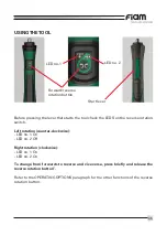
Page 35: ...ise LED no 1 On LED no 2 Off Right rotation clockwise LED no 1 On LED no 2 On To change from forwards to reverse and vice versa press briefly and release the reverse rotation button Refer to the OPERATING OPTIONS paragraph for the other functions of the reverse rotation button LED no 1 LED no 2 Forward reverse rotation button Start lever ...
Page 36: ... the screwdriver provided into the slot in the shell of the tool To access the adjustment ring slide the door covering the slot downwards see fig 1 Turn the screwdriver counter clockwise to increase torque or clockwise to reduce it see fig 2 and 3 For the E8C RE range The clutch is set by turning the adjustment ring at the rear of the tool Turn the ring anticlockwise to increase the tor que and cl...

Page 37: ... THE MODEL MAXIMUM TORQUE FOR THE MODEL MAXIMUM TORQUE FOR THE MODEL MAXIMUM TORQUE FOR THE MODEL MAXIMUM TORQUE FOR THE MODEL ADJUSTMENT LIMIT ADJUSTMENT LIMIT ADJUSTMENT LIMIT ADJUSTMENT LIMIT Fig 5 A B MAXIMUM TORQUE FOR THE SPECIFIED 8 ADJUSTMENT LIMIT MAXIMUM TORQUE FOR THE MODEL MAXIMUM ADJUSTMENT LIMIT FOR THE SPECIFIED MODEL compressing the spring further will cause the tool to stall witho...

Page 38: ...IMIT MAXIMUM TORQUE FOR THE MODEL MAXIMUM ADJUSTMENT LIMIT FOR THE SPECIFIED MODEL compressing the spring further will cause the tool to stall without triggering the ADJUSTMENT LIMIT A B C 2 4 6 8 10 NB in the example with the blue line the reference torque between 3 5 Nm and 4 Nm only applies to 650 rpm and 350 rpm tools The maximum adjustment limit is exceeded tool stalls clutch does not trigger...

Page 39: ...unner motor to gain access to the adjuster ring slide the spring see fig 1 Turn the nutrun ner motor counter clockwise to increase torque or clockwise to reduce it see fig 2 CAUTION While using the screwdriver nutrunner motor ALWAYS keep the clutch adjustment slot closed Failure to follow this rule could lead to personal injury or damage to objects Do not switch on or start the screwdriver nutrunn...

Page 40: ...o start maintained It is not necessary to keep pressure on the lever releasing the Push to start will trigger an error Function managed in the TPU M1 monitoring unit Enables disables the light over the work area while the screwdriver is rotating Resets the front flashing light when 1 000 000 cycles have been reached Enables disables untightening Screwdriver will gradually reach 100 of set speed in...

Page 41: ... once you have entered the SMART PRO menu keep the lever pressed for at least 3 seconds Some of the aforementioned starting methods may not be available for the whole range Fig 3 Fig 1 Fig 2 Before starting work hold the tool firmly as shown in figure 1 For torques in excess of 4Nm clamp the tool to a reaction arm the body of the tool can be clamped figure 3 or the specific ring can be used figure...

Page 42: ...ve in the area shown in figure 1 Do not clamp nutrunner motor at other points because this could dama ge it and compromise its working operation in such case Fiam cannot be held responsible for any damage to nutrunner motor CLAMPING THE NUTRUNNER MOTOR Fig 1 ...

Page 43: ...pply unit Power supply unit with integrated input output signals TPU 1 TPU 2 686200100 686200101 DESCRIPTION OF THE POWER SUPPLY UNIT Led 1 Led 2 Led 3 Led 4 Led S3 Led S1 Led S2 Led H Led L Speed setting button Power socket I O Port only for TPU 2 model Power ...

Page 44: ... tool speed Emergency input active only on TPU 2 model equipped with inputs outputs Tool connected and ready for use Tool rotating RUN Led 1 Led 2 Led 3 Led 4 Led H Led L Led S1 Led S2 Led S3 Green Red Red Green Green Green Yellow Yellow Yellow SPEED SETTING BUTTON INFORMATION Press this button to change from H high speed to L low speed and vice versa The tightening untightening speeds can be set ...

Page 45: ...ect command Signal that untightening is On Signal that the clutch has been triggered Signal that the tool is connected to the unit and ready for use Not connected RESERVED 1 2 3 4 5 6 7 8 9 10 11 12 13 14 15 CUSTOMER CONNECTION EMERGENCY INPUT USED EMERGENCY INPUT NOT USED DEFAULT Stop motor Tighten Untighten H L Speed Error Untightening Rotation Clutch trigger 24V I O Ready I O Ground Not connect...

Page 46: ... you detect an increase in noise from the tool or more generally a decrease in efficiency we recommend stopping the tool and taking it to a Fiam au thorised service centre for maintenance Acting promptly to grease the unit properly will protect the components from damage due to wear and prevent related issues CAUTION below there is a list of factors that can contribute individually or com bined to...

Page 47: ...y 1 000 000 cycles to remind about routine maintenance on the nutrunner motor It may be necessary to carry out maintenance ahead of the scheduled times in espe cially heavy usage conditions Specific conditions environmental or usage could alter correct reduction unit ope ration over time if you detect an increase in noise from the nutrunner motor or more generally a decrease in efficiency we recom...

Page 48: ...front light does not work The screwdriver does not run in reverse it does not untighten The screwdriver starts slowly The screwdriver starts untightening and then reverses direction 4 turns The screwdriver reaches the torque and then reverses direction 4 turns PART A possible issues associated with SMART PRO programming POSSIBLE CAUSE Option 2 is active push to start Option 3 is active lever start...

Page 49: ...cle The torque exceeds the maximum limit for the screwdriver or the cycle frequency is too high see the Operation and Maintenance Manual The torque exceeds the maximum limit for the screwdriver Check that the TPU is not set to LO speed POSSIBLE SOLUTION Carry out scheduled maintenance or reset the front light by following the instructions in the Operation and Maintenance Manual Switch off the syst...

Page 50: ...f the nutrunner motor with special screws self forming self perforating self tapping NUTRUNNER MOTOR FAQ PROBLEM FOUND The Low and High LEDs continue to flash when the nutrunner motor is connected to the power supply The nutrunner motor clutch does not perform the single click and does not stop until the control is released The TPU indicates a NOK result for each tightening operation red X The nut...

Page 51: ... 900 E8C4A30 650 E8C5A30 350 broches de vissage électriques E8MC1A 1200 E8MC1A 900 E8MC1A 650 E8MC2A 2000 E8MC3A 1200 E8MC3A 900 E8MC4A 650 E8MC5A 350 FIAM Utensili Pneumatici S p A Vicenza Italie déclare sous sa responsabilité exclusive que le produit auquel cette Déclaration se réfère est conforme à ce qui est prévu par les directives Directive machines 2006 42 CE Directive Compatibilité Électro...

Page 52: ...OPTIONS DE FONCTIONNEMENT 64 POIGNÉE DE L OUTIL ET MONTAGE SUR BRAS DE RÉACTION 65 BLOCAGE DE LA BROCHE DE VISSAGE 66 MODÈLE DISPOSITIF D ALIMENTATION 67 DESCRIPTION DU DISPOSITIF D ALIMENTATION 67 INFORMATIONS LED DISPOSITIF D ALIMENTATION 68 INFORMATIONS BOUTON DE PARAMÉTRAGE DE LA VITESSE 68 CONNECTEUR ENTRÉES SORTIES UNIQUEMENT POUR MODÈLE TPU 2 69 CARACTÉRISTIQUES TECHNIQUES DU DISPOSITIF D A...

Page 53: ...N RISQUE DE DANGER L opérateur devra consulter ce manuel à chaque fois qu il verra ce symbole de danger OBLIGATION DE LECTURE DU MANUEL Lire cette notice d instructions avant d utiliser l outil EPA La visseuse est conforme à la norme IEC 61340 5 1 Il est donc possible de l utiliser à l intérieur des zones EPA Electrostatic Protected Area MARQUE CE Le produit est conforme aux directives européennes...

Page 54: ...re masse Des fiches non modifiées et des prises correspondantes réduira le risque de décharge électrique b N utilisez pas le câble N utilisez jamais le câble pour transporter tirer ou dé brancher l outil électrique de la prise de courant Tenez le cordon à l écart des sources de chaleur de l huile des bords tranchants ou des pièces en mouve ment Si votre corps est en contact avec une terre ou une m...

Page 55: ...ectrique dans des situations imprévues f Portez des vêtements de travail appropriés Ne portez pas de vêtements amples ou de bijoux Maintenez les cheveux les vêtements et les gants éloignés des parties en rotation Les pièces en mouvement peuvent happer les vêtements amples les bijoux et les cheveux longs g En cas de branchement nécessaire de dispositifs à des installations d extraction et de récupé...

Page 56: ...aces de prise sèches et propres sans huiles ni graisses Les poignées glissantes ne garantissent pas une prise sûre et le contrôle de l outil dans les situations imprévues 5 Assistance a Faites réparer l outil électrique uniquement par des techniciens qualifiés et utilisez exclusivement des pièces de rechange identiques Cela permet de ga rantir une sécurité permanente de l outil électrique 6 Autre ...

Page 57: ... 320 340 170 0 6 0 6 0 6 0 6 0 6 2 5 3 0 3 5 4 0 4 5 E8C2A30 2000 E8C3A30 1200 E8C3A30 900 E8C4A30 650 E8C5A30 350 111712035 111712036 111712037 111712038 111712039 MODÈLES D ANGLE 90 MODÈLES DROITS MODÈLES D ANGLE 30 1180 980 870 740 640 530 2000 1650 1180 980 870 740 640 530 340 285 0 3 0 3 0 3 0 6 0 6 0 6 0 6 0 6 1 6 1 6 1 6 2 5 3 0 3 5 4 0 4 5 E8MC1A 1200 E8MC1A 900 E8MC1A 650 E8MC2A 2000 E8MC...

Page 58: ...z tout d abord le câble d alimentation de l outil fourni avec l équipement au connecteur circulaire de l outil reliez ensuite l autre extrémité du câble au con necteur circulaire présent sur la façade du dispositif d alimentation 2 Raccordez le câble d alimentation du dispositif d alimentation à la fiche située sur l arrière du dispositif d alimentation Branchez ensuite l outil au réseau d aliment...

Page 59: ...D n 2 éteinte Rotation droite horaire LED n 1 allumée LED n 2 éteinte Pour passer de la rotation droite à la rotation gauche et vice versa pressez et relâchez rapidement le bouton inversion sens de rotation Pour les autres fonctions du bouton d inversion du sens de rotation on renvoie au paragraphe OPTIONS DE FONCTIONNEMENT LED n 1 LED n 2 Bouton d inversion sens de rotation Levier de démarrage ...

Page 60: ...lle Pour accéder à la bague de réglage il faut faire coulisser le couvercle de la fente vers le bas voir fig 1 Pour augmenter le couple tournez le tournevis dans le sens anti horaire pour le diminuer tournez le dans le sens horaire voir fig 2 et 3 Pour la gamme E8C RE Le réglage de l embrayage s effectue en tournant la bague de réglage située dans la partie arrière de l outil Pour aug menter le co...

Page 61: ... LIMITE DE RÉGLAGE LIMITE DE RÉGLAGE COUP 111712070 111712071 111712072 111712073 111712074 9 COUPLE MINIMAL COUPLE MAXIMAL MODÈLE COUPLE MAXIMAL MODÈLE COUPLE MAXIMAL MODÈLE COUPLE MAXIMAL MODÈLE COUPLE MAXIMAL MODÈLE LIMITE DE RÉGLAGE LIMITE DE RÉGLAGE LIMITE DE RÉGLAGE LIMITE DE RÉGLAGE A B COUPLE MAXIMAL POUR LE MODÈLE 8 LIMITE DE RÉGLAGE COUPLE MAXIMAL MODÈLE LIMITE DE RÉGLAGE MAXIMALE POUR L...

Page 62: ...IENS LE COUPLE INDICATIF 1 2 3 LIMITE DE RÉGLAGE COUPLE MAXIMAL MODÈLE LIMITE DE RÉGLAGE MAXIMALE POUR LE MODÈLE INDIQUÉ si l on comprime encore plus le ressort l outil se bloque et l embrayage ne LIMITE DE RÉGLAGE A B C 2 4 6 8 10 N B dans l exemple avec ligne bleue la référence de couple entre 3 5 Nm et 4 Nm est valable uniquement pour des outils à 650 tr min et 350 tr min Pour les autres outils...

Page 63: ... bague de réglage il est nécessaire de faire coulisser la fente vers le bas voir la fig 1 Pour augmenter le couple tournez le tournevis dans le sens anti horaire pour le diminuer tournez le dans le sens horaire voir fig 2 ATTENTION Durant le fonctionnement maintenez TOUJOURS la fente de réglage de l em brayage fermée Le non respect de cette norme peut entraîner de sérieux dommages aux personnes et...

Page 64: ...pression sur le levier le relâchement de la poussée génère une erreur Fonction gérée dans l unité d alimentation et de surveillance TPU M1 Active désactive l éclairage de la zone de travail durant la rotation Cette fonction remet à zéro le clignotement de l é clairage frontal lorsque l outil a atteint 1 000 000 de cycles Active désactive le dévissage Démarrage lent de la visseuse de l arrêt à la v...

Page 65: ...s êtes entré dans le menu SMART PRO maintenez le levier enfoncé pendant au moins 3 secondes Certains modes de démarrage susmentionnés pourraient ne pas être disponibles dans toutes les gammes Fig 3 Fig 1 Fig 2 Avant le démarrage saisir fermement l outil comme indiqué dans la figure 1 Pour des couples supérieurs à 4 Nm fixez l outil sur un bras de réaction le ver rouillage peut être effectué sur le...

Page 66: ... fixez pas à des points de la broche de vissage différents de ceux indiqués car cela pourrait entraîner des dommages sur la broche de vis sage en question et compromettre son fonctionnement le cas échéant Fiam ne peut être tenue pour responsable des dommages subis par la broche de vissage BLOCAGE DE LA BROCHE DEVISSAGE Fig 1 ...

Page 67: ...imentation avec des signaux d entrée sortie intégrés TPU 1 TPU 2 686200100 686200101 DESCRIPTION DU DISPOSITIF D ALIMENTATION Led 1 Led 2 Led 3 Led 4 Led S3 Led S1 Led S2 Led H Led L Bouton de paramétrage de la vitesse Prise d alimentation Connecteur I O uniquement pour modèle TPU 2 Power ...

Page 68: ...e Entréed urgenceactive uniquementsurlemodèleTPU2 équipéd entrées sorties Outil branché et prêt à l emploi Outil en rotation RUN Led 1 Led 2 Led 3 Led 4 Led H Led L Led S1 Led S2 Led S3 Vert Rouge Rouge Vert Vert Vert Jaune Jaune Jaune INFORMATIONS BOUTON DE PARAMÉTRAGE DE LA VITESSE La pression du bouton permet de passer de la vitesse H élevée à la vitesse L basse les vitesses de vissage dévissag...

Page 69: ...n de la vitesse élevée basse Signalement que le dévissage est actif Signalement que l embrayage s est déclenché Signalement qu un outil est raccordé à la base et prêt à l emploi Non raccordé RÉSERVÉ 1 2 3 4 5 6 7 8 9 10 11 12 13 14 15 Déclenchement embrayage CONNEXION CLIENT ENTRÉE URGENCE UTILISÉE ENTRÉ URGENCE NON UTILISÉ PAR DÉFAUT Arrêt moteur Visse Dévisse Vitesse H L Erreur Dévissage Rotatio...

Page 70: ...n fonc tionnement plus bruyant de l outil ou de manière plus générale une perte d effica cité il est conseillé d arrêter l outil et de la soumettre à une révision dans un Centre agréé Fiam Une intervention rapide de rétablissement des conditions de graissage idéales des groupes préservera les composants contre les dommages liés à l usure et évitera l apparition de problèmes connexes ATTENTION nous...

Page 71: ...enance préventive de la broche de vissage Si les conditions d utilisation sont particulièrement difficiles il pourrait être nécessai re d anticiper la maintenance par rapport aux intervalles programmés Des conditions particulières ambiantes ou d utilisation pourraient altérer dans le temps le fonctionnement correct des groupes de réduction si l on constate un fon ctionnement plus bruyant de la bro...

Page 72: ...tionne pas La visseuse n inverse pas le mouvement elle ne dévisse pas La visseuse démarre lentement La visseuse démarre en dévissage puis inverse le mouvement 4 tours La visseuse atteint le couple puis inverse la rotation 4 tours PARTIE A anomalies possibles liées à la programmation avec SMART PRO CAUSE PROBABLE L option 2 est active démarrage par poussée L option 3 est active démarrage à levier p...

Page 73: ...our la visseuse ou fréquence cycle trop élevée cf Manuel d utilisation et de maintenance Couple supérieur à la limite maximale prévue pour la visseuse Vérifier si la vitesse LO a été sélectionnée sur l unité TPU SOLUTION POSSIBLE Prévoir une maintenance programmée ou réinitialiser la lumière frontale suivant les instructions sur le Manuel d utilisation et de maintenance Éteindre et rallumer le sys...

Page 74: ... utilisation de la broche de vissage avec des vis particulières trilobées autoforeu ses autotaraudeuses FAQ BROCHES DE VISSAGE PROBLÈME TROUVÉ En connectant la broche de vissage au dispositif d alimentation les voyants Low et High continuent à clignoter La broche de vissage n effectue pas le déclenchement à l embrayage et ne s arrête pas tant que la commande n est pas relâchée À chaque vissage l u...

Page 75: ...30 900 E8C4A30 650 E8C5A30 350 motores eléctricos para atornillar E8MC1A 1200 E8MC1A 900 E8MC1A 650 E8MC2A 2000 E8MC3A 1200 E8MC3A 900 E8MC4A 650 E8MC5A 350 FIAM Utensili Pneumatici S p A Vicenza Italia declara bajo su exclusiva responsabilidad que el producto al que se refiere esta declaración cumple con las disposiciones de las directivas siguientes Directiva de máquinas 2006 42 CE Directiva Com...

Page 76: ...RA ATORNILLAR 87 OPCIONES DE FUNCIONAMIENTO 88 EMPUÑADURA DE LA HERRAMIENTA Y MONTAJE EN BRAZO DE REACCIÓN 89 FIJACIÓN DEL MOTOR PARA ATORNILLAR 90 MODELOS DE ALIMENTADOR 91 DESCRIPCIÓN DEL ALIMENTADOR 91 INFORMACIÓN LED ALIMENTADOR 92 INFORMACIÓN PULSADOR DE REGULACIÓN DE LA VELOCIDAD 92 CONECTOR ENTRADAS SALIDAS SOLO PARA EL MODELO TPU 2 93 CARACTERÍSTICAS TÉCNICAS DEL ALIMENTADOR 94 MANTENIMIEN...

Page 77: ...o ATENCIÓN RIESGO DE PELIGRO El operador debe consultar este manual cada vez que vea este símbolo de peligro OBLIGACIÓN DE LEER EL MANUAL Lea el manual de instrucciones antes de utilizar el producto EPA El atornillador cumple con la norma IEC 61340 5 1 por lo tanto es posible utilizarlo dentro de las áreas EPA Área de protección electrostática MARCA CE El producto cumple con las directivas europea...

Page 78: ...on her ramientas eléctricas equipadas con puesta a tierra a masa Las clavijas no modificadas y los enchufes correspondientes reducen el riesgo de descarga eléctrica b Evite el contacto del cuerpo con superficies conectadas a tierra o a masa tales como tuberías radiadores cocinas y frigoríficos Si su cuerpo está haciendo tierra o masa aumenta el riesgo de descarga eléctrica c No exponga las herrami...

Page 79: ... stas f Use prendas de trabajo adecuadas No lleve prendas anchas ni joyas Manten ga los cabellos prendas y guantes lejos de las piezas móviles La ropa ancha las joyas o el cabello largo pueden engancharse en las piezas móviles g Si se tuvieran que conectar dispositivos a sistemas de extracción y recolección de polvo asegúrese de que los mismos estén conectados y que se utilicen de manera adecuada ...

Page 80: ...s peligrosas h Mantenga la empuñadura y las otras superficies de agarre secas y limpias de aceite y grasa Las empuñaduras resbaladizas no garantizan un agarre seguro ni el control de la herramienta en situaciones imprevistas 5 Servicio de asistencia a Haga reparar la herramienta solo a un técnico cualificado y utilice únicamente piezas de repuesto idénticas Esto garantiza la seguridad constante de...

Page 81: ...35 640 320 340 170 0 6 0 6 0 6 0 6 0 6 2 5 3 0 3 5 4 0 4 5 E8C2A30 2000 E8C3A30 1200 E8C3A30 900 E8C4A30 650 E8C5A30 350 111712035 111712036 111712037 111712038 111712039 MODELOS ANGULARES 90 MODELOS RECTOS MODELOS ANGULARES 30 1180 590 870 435 640 320 2000 1000 1180 590 870 435 640 320 340 170 0 3 0 3 0 3 0 6 0 6 0 6 0 6 0 6 1 6 1 6 1 6 2 5 3 0 3 5 4 0 4 5 E8C1ARE 1200 E8C1ARE 900 E8C1ARE 650 E8C...

Page 82: ...ntación de la herramienta suministrado de serie primero al conector circular de la herramienta y luego conecte el otro extremo del cable al conector circular presente en el frente del alimentador 2 Conecte el cable de alimentación del alimentador al conector situado en la parte trasera del alimentador Luego conecte el producto a la red de alimentación y enciéndalo Fiam recomienda utilizar el atorn...

Page 83: ...LED 2 apagado Rotación derecha sentido horario LED 1 encendido LED 2 apagado Para cambiar la rotación de derecha a izquierda y viceversa presione y suelte rápi damente el pulsador de inversión del sentido de rotación Consulte el apartado OPCIONES DE FUNCIONAMIENTO para las otras funciones del pulsador de inversión del sentido de rotación LED n 1 LED n 2 Pulsador de inversión del sentido de rotació...

Page 84: ... de la cubierta exterior Para acceder al casquillo de regulación es necesario deslizar la tapa que cubre la ranura hacia abajo véase la fig 1 Para aumentar el par gire el destornillador en sentido antihorario para disminuirlo gíre el destornillador en sentido horario véase las fig 2 y 3 Para la gama E8C RE en la parte delantera de la herramienta Para aumentar el par gire el destornillador en senti...

Page 85: ...N 3 LÍMITE DE REGULACIÓN LÍMITE DE REGULACIÓN PA 111712070 111712071 111712072 111712073 111712074 9 PAR MÍNIMO PAR MÁXIMO MODELO PAR MÁXIMO MODELO PAR MÁXIMO MODELO PAR MÁXIMO MODELO PAR MÁXIMO MODELO LÍMITE DE REGULACIÓN LÍMITE DE REGULACIÓN LÍMITE DE REGULACIÓN LÍMITE DE REGULACIÓN A B PAR MÁXIMO PARA EL MODELO INDICADO 8 LÍMITE DE REGULACIÓN PAR MÁXIMO MODELO LÍMITE MÁXIMO DE REGULACIÓN PARA E...

Page 86: ...ICATIVO ordenada 1 2 3 LÍMITE DE REGULACIÓN PAR MÁXIMO MODELO LÍMITE MÁXIMO DE REGULACIÓN PARA EL MODELO INDICADO si se comprime más el muelle la herramienta se bloquea y el embrague no LÍMITE DE REGULACIÓN A B C 2 4 6 8 10 NOTA en el ejemplo con la línea azul la referencia de par entre 3 5 Nm y 4 Nm es válida solo para herramientas de 650 rpm y 350 rpm Para las otras herramientas 2000 rpm 1200 rp...

Page 87: ...r al casquillo de regulación es necesario deslizar el muelle con banda giratoria véase la fig 1 Para aumentar el par gire el destornillador en sentido antihorario para disminuirlo gírelo en sentido horario véase la fig 2 ATENCIÓN Durante el funcionamiento SIEMPRE mantenga cerrada la ranura de regulación del embrague El incumplimiento de esta regla puede pro vocar daños a personas y o bienes No enc...

Page 88: ...re sionada la palanca la liberación del empuje genera un error Función gestionada en la unidad de alimentación y monitorización TPU M1 Activa desactiva la luz de la zona de trabajo durante la rotación Restablece el parpadeo de la luz frontal cuando se alcanzan 1 000 000 de ciclos Activa desactiva el desatornillado Inicio lento del atornillador de parada a velocidad no minal en aproximadamente 1 5 ...

Page 89: ... haya ingresado al menú SMART PRO mantenga presionada la palanca durante al menos 3 segundos Algunos modos de arranque antes mencionados podrían no estar disponibles en todas las gamas Fig 3 Fig 1 Fig 2 Antes del arranque sujete firmemente la herra mienta como se muestra en la figura 1 Para pa res superiores a 4 Nm fije la herramienta a un brazo de reacción la fijación se puede realizar en la cubi...

Page 90: ... la zona indicada en la figura 1 No fije el motor para atornillar en otros puntos porque podría dañar el motor para atornillar y comprometer su funcionamiento en dicho caso Fiam no se hace responsable por daños causados al motor para atornillar FIJACIÓN DEL MOTOR PARA ATORNILLAR Fig 1 ...

Page 91: ... de alimentación con señales de entrada salida integradas TPU 1 TPU 2 686200100 686200101 DESCRIPCIÓN DEL ALIMENTADOR Led 1 Led 2 Led 3 Led 4 Led S3 Led S1 Led S2 Led H Led L Pulsador para seleccionar la velocidad Conector de alimentación Conector I O solo para el modelo TPU 2 Power ...

Page 92: ...rgencia activa solo en el modelo TPU 2 equipado con entradas salidas Herramienta conectada y lista para usar Herramienta girando RUN Led 1 Led 2 Led 3 Led 4 Led H Led L Led S1 Led S2 Led S3 Verde Rojo Rojo Verde Verde Verde Amarillo Amarillo Amarillo INFORMACIÓN PULSADOR DE REGULACIÓN DE LA VELOCIDAD Al presionar el pulsador se puede pasar desde la velocidad H rápida a la velocidad L lenta las vel...

Page 93: ...aja Señala que se ha activado el desatornillado Señala que se ha activado el embrague Señalaqueunaherramientaestáconectadaalabaseyestálistaparaeluso No conectada RESERVADO 1 2 3 4 5 6 7 8 9 10 11 12 13 14 15 CONEXIÓN CON EL CLIENTE ENTRADA EMERGENCIA UTILIZADA ENTRADA DE EMERGENCIA NO UTILIZADA PREDETERMINADO Parada motor Atornilla Desatornilla Velocidad H L Error Desatornillado Rotación Activació...

Page 94: ...to en el nivel de ruido de la herramienta en general una pérdida de eficiencia es acon sejable detener la herramienta y llevarla a un Centro Fiam autorizado para el mante nimiento Un restablecimiento inmediato de las condiciones ideales de engrase de las unidades protegerá los componentes de los daños causados por el desgaste y evitará que aparezcan los problemas correspondientes ATENCIÓN La sigui...

Page 95: ...acer el mantenimiento ordinario del mismo En el caso de que las condiciones de uso sean particularmente pesadas puede ser necesario anticipar el mantenimiento con respecto a los intervalos programados Las condiciones especiales ambientales o de uso podrían alterar el funcionamiento correcto de los grupos de reducción a lo largo del tiempo si se percibe un aumento en el nivel de ruido del motor par...

Page 96: ...uz frontal no funciona El atornillador no invierte el movimiento no desenrosca El atornillador arranca lentamente Elatornilladorarrancadesatornillandoy despuésinvierteelmovimiento 4vueltas El atornillador alcanza el par y después invierte la rotación 4 vueltas PARTE A posibles desperfectos asociados a la programabilidad con SMART PRO POSIBLE CAUSA Está activa la opción 2 arranque por empuje Está a...

Page 97: ...iclo El par supera el límite máximo establecido para el atornillador o la frecuencia del ciclo es demasiado alta consulte el Manual de Uso y Mantenimiento El par es superior al límite máximo previsto para el atornillador Compruebe que en la TPU no esté configurada la velocidad LO POSIBLE SOLUCIÓN Realice el mantenimiento programado o reajuste la luz frontal siguiendo las instrucciones del Manual d...

Page 98: ...uso del motor para atornillar con tornillos especiales trilobulado autoperforantes autorroscantes PREGUNTAS FRECUENTES SOBRE LOS PROBLEMAS DEL MOTOR PARA ATORNILLAR PROBLEMA OBSERVADO Al conectar el atornillador al alimentador los LED Low y High siguen parpadeando El atornillador no realiza la liberación del embrague y no se detiene hasta que se suelta el mando Cada vez que se atornilla la TPU ind...

Page 99: ... elektrische Einbauschrauber E8MC1A 1200 E8MC1A 900 E8MC1A 650 E8MC2A 2000 E8MC3A 1200 E8MC3A 900 E8MC4A 650 E8MC5A 350 Wir FIAM Utensili Pneumatici S p A Vicenza Italien erklären unter unserer alleinigen Verantwortung dass das Produkt auf das sich diese Erklärung bezieht den Bestimmungen der folgenden Richtlinien entspricht Maschinenrichtlinie 2006 42 CE Richtlinie zur elektromagnetischen Verträg...

Page 100: ...REGULIERUNG DES EINBAUSCHRAUBERS 111 FUNKTIONSOPTIONEN 112 GRIFF DES WERKZEUGS UND MONTAGE AUF DREHMOMENTABSTUTZUNG 113 HALTERUNG DES EINBAUSCHRAUBERS 114 MODELLE NETZGERÄT 115 BESCHREIBUNG NETZGERÄT 115 LED INFORMATIONEN NETZGERÄT 116 INFORMATIONEN TASTE GESCHWINDIGKEITSEINSTELLUNG 116 ANSCHLUSS AUSGÄNGE EINGÄNGE NUR FÜR MODELL TPU 2 117 TECHNISCHE DATEN DER NETZGERÄT 118 WARTUNG DES WERKZEUGS 11...

Page 101: ...ON Der Bediener muss diese Anleitung lesen wenn er dieses Gefahrensymbol sieht PFLICHT DIE BEDIENUNGSANLEITUNG ZU LESEN Bitte lesen Sie diese Bedienungsanleitung bevor Sie das Produkt verwenden EPA Der Schrauber entspricht der Norm IEC 61340 5 1 Er kann daher im elektrostatisch geschützten Bereich EPA eingesetzt werden CE ZEICHEN Das Produkt entspricht den geltenden europäischen Richtlinien ...

Page 102: ...er verwendet werden Nicht veränderte Ste cker und entsprechende Steckdosen verringern die Gefahr eines Stromschlags b Vermeiden Sie den Kontakt des Körpers mit geerdeten Oberflächen wie Rohren Heizkörpern Küchen und Kühlschränken Wenn Ihr Körper mit der Erde oder der Masse in Berührung kommt steigt die Gefahr eines Stromschlags c Elektrowerkzeuge nicht dem Regen aussetzen und nicht in feuchten Räu...

Page 103: ...Situationen besser kontrollieren f Tragen Sie angemessene Kleidung Tragen Sie keine lose Kleidung oder Schmuck Halten Sie Haare Kleidung und Handschuhe von beweglichen Teilen fern Weite Kleidung Schmuck oder lange Haare können sich in beweglichen Teilen verfangen g Sind Geräte vorhanden die an Entstaubungs und Absauganlagen angeschlossen werden sollen dann stellen Sie sicher dass diese ordnungsgem...

Page 104: ... Griffflächen trocken öl und fettfrei Rutschige Griffe bieten keinen sicheren Halt und keine Kontrolle des Werkzeugs in unerwar teten Situationen 5 Kundendienst a Lassen Sie das Elektrowerkzeug nur von qualifizierten Technikern reparieren und verwenden Sie nur identische Ersatzteile Dadurch wird sichergestellt dass das Elektrowerkzeug immer sicher ist 6 Sonstiges a Bei Drehmomenten größer als 4 Nm...

Page 105: ...0 170 0 6 0 6 0 6 0 6 0 6 2 5 3 0 3 5 4 0 4 5 E8C2A30 2000 E8C3A30 1200 E8C3A30 900 E8C4A30 650 E8C5A30 350 111712035 111712036 111712037 111712038 111712039 MODELLE MIT 90 WINKELKOPF GERADER GRIFF MODELLE MIT 30 WINKELKOPF 1180 590 870 435 640 320 2000 1000 1180 590 870 435 640 320 340 170 0 3 0 3 0 3 0 6 0 6 0 6 0 6 0 6 1 6 1 6 1 6 2 5 3 0 3 5 4 0 4 5 E8C1ARE 1200 E8C1ARE 900 E8C1ARE 650 E8C2ARE...

Page 106: ... Fiam gelieferten 1 Schließen Sie das mitgelieferte Netzkabel zuerst an den Rundstecker des Werkzeugs und dann das andere Ende des Netzkabels an den Rundstecker auf der Frontplatte der Netzgerät an 2 Schließen Sie das Netzkabel an die Buchse auf der Rückseite der Netzgerät an Schließen Sie dann das Gerät an das Stromnetz an und schalten Sie es ein Fiam empfiehlt die Verwendung des Schraubers Einba...

Page 107: ...Nr 1 leuchtet LED Nr 2 ausgeschaltet Rechtslauf im Uhrzeigersinn LED Nr 1 leuchtet LED Nr 2 ausgeschaltet UmzwischenRechts undLinkslaufumzuschalten dieTaste Drehrichtungsumkehr schnell drücken und loslassen Die weiteren Funktionen derTaste zum Umkehren der Drehrichtung entnehmen Sie bitte dem Abschnitt FUNKTIONSOPTIONEN LED nr 1 LED nr 2 Taste Drehrichtungsumkehr Starthebel ...

Page 108: ...zugreifen die Tür die den Schlitz abdeckt nach unten schieben siehe Abb 1 Zum Erhöhen des Anziehmoments den Schraubendreher gegen den Uhrzeigersinn drehen und ihn zum Senken des Anziehmoments im Uhrzeigersinn drehen siehe Abb 2 und 3 Für die Baureihe E8C RE Die Kupplungseinstellung wird durch Drehen der am vorde ren Teil des Werkzeugs angebrachten Einstellmutter erreicht Zum Erhöhen des Anziehmome...

Page 109: ...INSTELLGRENZE MAX 111712070 111712071 111712072 111712073 111712074 9 MINIMALES DREHMOMENT MAXIMALES DREHMOMENT MODELL MAXIMALES DREHMOMENT MODELL MAXIMALES DREHMOMENT MODELL MAXIMALES DREHMOMENT MODELL MAXIMALES DREHMOMENT MODELL EINSTELLGRENZE EINSTELLGRENZE EINSTELLGRENZE EINSTELLGRENZE A B MAXIMALES DREHMOMENT FÜR DAS 8 EINSTELLGRENZE MAXIMALES DREHMOMENT MODELL MAXIMALE EINSTELLGRENZE FÜR DAS...

Page 110: ...OMENT RICHTWERTS Ordinate 1 2 3 EINSTELLGRENZE MAXIMALES DREHMOMENT MODELL MAXIMALE EINSTELLGRENZE FÜR DAS ANGEGEBENE MODELL wird die Feder weiter zusammengedrückt sperrt das Werkzeug und die Kupplung löst EINSTELLGRENZE A B C 2 4 6 8 10 Hinweis Im Beispiel mit blauer Linie gilt die Drehmoment Referenz zwischen 3 5 Nm und 4 Nm nur für Werkzeuge mit 650 U Min und 350 U Min Bei den anderen Werkzeuge...

Page 111: ...unten geschoben werden siehe Abb 1 Zum Erhöhen des Anziehmoments den Schraubendreher gegen den Uhrzeigersinn drehen und ihn zum Senken des Anziehmoments im Uhrzeigersinn drehen siehe Abb 2 ACHTUNG Halten Sie den Kupplungseinstellschlitz während des Betriebs IMMER ge schlossen Die Nichteinhaltung dieser Regel kann zu Personenund oder Sa chschäden führen Den Schrauber Einbauschrauber nicht einschalt...

Page 112: ...Beenden des Schubs erzeugt einen Fehler Funktion verwaltet in der TPU M1 Stromversorgungs und Überwachungseinheit Aktiviert deaktiviert die Beleuchtung des Arbeitsbereichs wäh rend der Drehung Setzt das Aufleuchten des Frontlichts zurück wenn 1 000 000 Zyklen erreicht sind Aktiviert deaktiviert das Abschrauben Langsames Anlaufen des Schraubers vom Stillstand bis zur Nenndrehzahl in ca 1 5 Sekunden...

Page 113: ...erufen haben halten Sie den Hebel minde stens 3 Sekunden lang gedrückt Einige der oben genannten Startmodi sind möglicherweise nicht bei allen Baureihen verfügbar Abb 3 Abb 1 Abb 2 Das Werkzeug vor dem Starten fest fassen wie in Abbildung 1 gezeigt Bei Drehmomenten größer als 4 Nm muss das Werkzeug auf eine Drehmo mentstütze geklemmt werden Die Klemmung kannaufderSchale Abbildung3 oderaufderspe zi...

Page 114: ...tlang der Außenschale eingespannt werden Nicht an anderen Stellen des Einbauschraubers spannen da dies das Werkzeug beschädigen und seine Funktionalität beeinträchtigen kann In diesem Fall haftet Fiam nicht für Schäden am Einbauschrauber HALTERUNG DES EINBAUSCHRAUBERS Abb 1 ...

Page 115: ...Netzgerät mit integrierten Eingangs Ausgangssignalen TPU 1 TPU 2 686200100 686200101 BESCHREIBUNG NETZGERÄT Led 1 Led 2 Led 3 Led 4 Led S3 Led S1 Led S2 Led H Led L Taste zum Auswählen der Drehzahl Stromversorgungsbuchse I O Anschluss nur für Modell TPU 2 Power ...

Page 116: ... nur bei Modell TPU 2 das mit Eingängen Ausgängen ausgestattet ist Werkzeug angeschlossen und verwendungsbereit Werkzeug dreht sich RUN Led 1 Led 2 Led 3 Led 4 Led H Led L Led S1 Led S2 Led S3 Grün Rot Rot Grün Grün Grün Gelb Gelb Gelb INFORMATIONEN TASTE ZUM AUSWÄHLEN DER DREHZAHL Durch Drücken der Taste kann zwischen den Geschwindigkeiten H schnell und L langsam umgeschaltet werden Die An Abschr...

Page 117: ...keit Signal dass die Abschraubung aktiv ist Signal dass die Kupplung ausgelöst hat Signal dass ein Werkzeug mit der Basis verbunden und einsatzbereit ist Nicht verbunden RESERVIERT 1 2 3 4 5 6 7 8 9 10 11 12 13 14 15 KUNDENVERBINDUNG NOTFALL EINGANG VERWENDET NOTRUF NICHT VERWENDET STANDARD Motorstopp Anschrauben Abschrauben Geschwindigkeit H L Fehler Abschraubung Drehung Kupplungsauslösung 24V I ...

Page 118: ...hpegels am Werkzeug oder eines allgemeinen Leistungsverlusts ist es ratsam den Werkzeug anzuhalten und ihn zur Wartung in ein autorisiertes Fiam Zentrum zu bringen Früh zeitige Maßnahmen zur Wiederherstellung der idealen Schmierbedingungen der Baugruppen schützen die Komponenten vor verschleißbedingten Schäden und ver hindern das Auftreten von Problemen ACHTUNG Nachfolgend finden Sie eine Liste vo...

Page 119: ...er auf die Notwendigkeit einer planmäßigen Wartung des Einbauschrau bers hinweist Bei besonders schweren Einsatzbedingungen kann es erforderlich sein die Wartung vor den geplanten Intervallen durchzuführen Besondere Bedingungen Umwelt oder Einsatzbedingungen können die ordnungs gemäße Funktion der Untersetzungsgetriebe im Laufe der Zeit beeinträch tigen Im Falle eines erhöhten Geräuschpegels am Ei...

Page 120: ...ewegung nicht um der Schrauber schraubt nicht ab der Schrauber startet langsam derSchrauberbeginntmitdemAbschraubenund kehrtdanndieBewegungum 4Umdrehungen derSchraubererreichtdasDrehmomentundkehrt danndieDrehungum 4Umdrehungen TEIL A Mögliche Anomalien in Zusammenhang mit der Programmierung über SMART PRO MÖGLICHE URSACHE Option 2 Start durch Druck ist aktiviert Option 3 Start mit Hebel Druck ist ...

Page 121: ...ze für den Schrauber oder die Zyklusfrequenz ist zu hoch vgl Betriebs und Wartungshandbuch Das Drehmoment ist höher als die maximale Drehmomentgrenze für den Schrauber Überprüfen dass am TPU nicht die niedrige Geschwindigkeit LO eingestellt ist MÖGLICHE LÖSUNG eine planmäßige Wartung vorsehen oder die Frontleuchte gemäß den Anweisungen im Betriebs und Wartungshandbuch zurücksetzen Das System aus u...

Page 122: ... speziellen Verbindungen Verwendung des Einbauschraubers mit Spezialschrauben Dreikant selbstboh rend selbstschneidend FAQ EINBAUSCHRAUBER ERKANNTES PROBLEM Beim Anschluss des Schraubers an die Stromversor gung blinken die LEDs L niedrig und H hoch weiterhin Der Einbauschrauber führt keine einzelne Kupplungsbetätigung aus und stoppt erst wenn die Steuerung losgelassen wird Bei jeder Verschraubung ...

Page 123: ......

Page 124: ...ent SystemCertificate EnvironmentalManagement SystemCertificate www fiamgroup com info fiamgroup com Fiam Utensili Pneumatici Spa Viale Crispi 123 36100 Vicenza Italy Tel 39 0444 385000 Fax 39 0444 385002 Fiam France Succursale 73 cours Albert Thomas 69003 Lyon France Tel 33 0 9 70 40 73 85 Fiam España Sucursal Travessera de Gràcia 11 5ªplanta 08021 Barcelona España Tel 34 636808112 Meet us on ete...

Reviews: