13
INSTALLATION
TECHNICAL NOTE FOR INSTALLER AND TECHNICAL MAINTENANCE
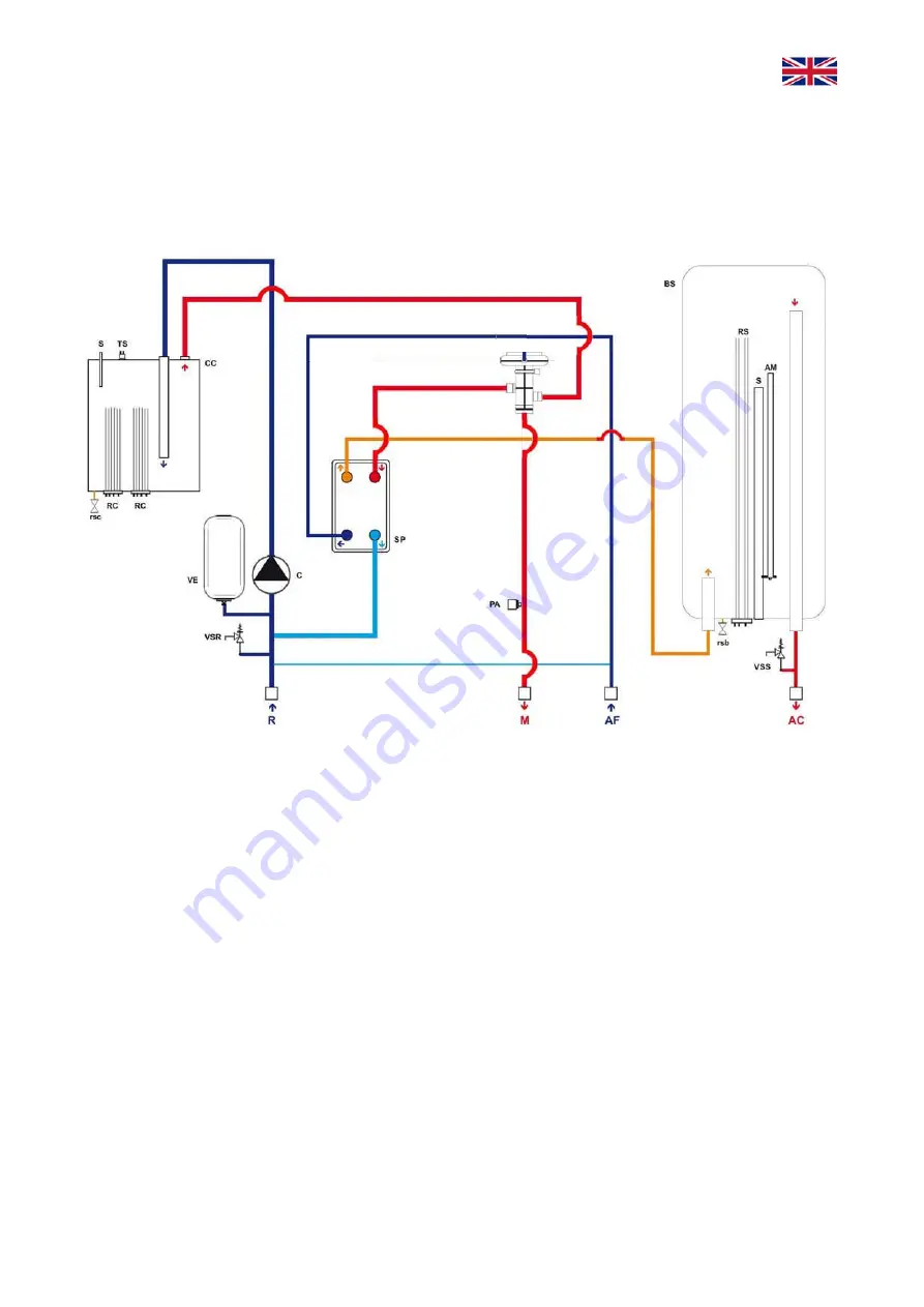
HYDRAULIC SCHEME
(
Ele
k
tra Compact
12 kW BP-L
016
version)
Legend
- TS
Safety
thermostat.
-
rs Filling
tap.
- VSS Safety valve sanitary circuit ½”x0,65 MPa (6,5 bar). - PA
Water pressure switch.
- VSR Safety valve heating circuit ½”x0,3 MPa (3 bar).
- AM Magnesium
anode.
- VE Expansion vessel heating circuit. - VDE Electric diverter valve.
- R
Hydraulic connection inlet heating circuit.
- RC
Boiler resistance 3/6 kW.
- M
Hydraulic connection outlet heating circuit.
- RS
Sanitary resistance 2 kW.
- rsc Drain valve of boiler body.
- CC
Boiler body.
- S
Thermowell for immersion sensor.
- rsb Drain valve of tank.
- AF
Hydraulic connection inlet sanitary (cold water).
- BS
Hot water storage tank 37 liters.
- AC
Hydraulic connection outlet sanitary (hot water).
- SP
Brazed heat exchangers.
For the other models, the only changes refer to the number of electric resistances; the 6 kW
version has two 3 kW resistances (detail RC), the 12 kW version has two 6 kW resistances, the 18
kW version has three 6 kW resistances and the 24 kW version has four 6 kW resistances.


