T4-5-14
EX355
COMPONENT TEST
MAIN PUMP FLOW RATE
Summary:
With a portable hydraulic tester installed at the main
pump delivery port to be measured, the flow rate is
measured to check the main pump performance using
both Dr.EX and a pressure gauge at the same time.
Preparation:
1. Stop the engine. Depress the air release valve on
top of the hydraulic oil tank to release any remain-
ing pressure. Connect a vacuum pump to the oil
filler of the hydraulic oil tank.
NOTE
: Continuously operate the vacuum pump while
connecting the portable tester to the main pump.
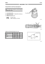
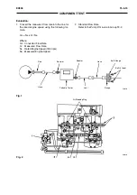
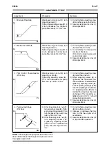
2. Disconnect the hose from the main pump to be
measured. Install pipe to the pump delivery port
with split flanges and bolts used to connect the
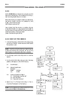
disconnected hose. (Refer to fig.1.)
: 10 mm
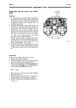
3. Connect a hose, an adapter, the portable tester
75298406
, a further adapter, joint, hose, and
flange to pipe. (Refer to fig.1.)
: 38 mm, 41 mm
4. Connect the hose removed in step 2 to flange using
flange and bolts (4 used). (Refer to fig.1.)
: 10 mm
5. Remove the pressure check port plug from the
main pump, and install adapter, hose and pressure
gauge. (Refer to T4-5-7.)
: 6 mm
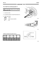
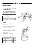
6. Remove regulator pipes (3 and 4). Connect the
removed pipe holes on the regulator to be meas-
ured with hose. Install plugs to the removed pipe
holes on the regulator not being measured. (Refer
to fig.2.)
7. Remove regulator pipe (5) from the regulator.
Install plug to the removed pipe end. Connect hose
to the removed pipe port on the regulator. Place a
container to receive the hydraulic oil flow during
measurement.
8. Disconnect hose (2) from the pump regulator to be
measured. Disconnect hose (1) from the top of the
pilot filter. Connect two ports from which hoses
(1 and 2) were removed with hose. (Refer to fig.2.)
: 22 mm
9.
Disconnect the vacuum pump. Loosen the air
bleeding plug on the pump casing to bleed air until
oil flows out of the plug clearance.
: 41 mm
10. Install a tachometer to the injection pipe. Discon-
nect N sensor. Fully open the loading valve on the
portable tester.
11. Start the engine Check the pressure gauge con-
nection for any oil leaks. Connect Dr. EX and
select the monitor function.
Measurement:
1. Measure the maximum flow rate.
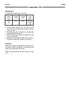
2. Select the following switch positions:
Engine Travel
E Mode HP Mode
Work
Auto-
Control Mode
Switch
Switch
Mode
Idle
Dial
Switch
Switch Switch
Fast
Fast
General
Idle
Mode
OFF
OFF
Purpose
OFF
Mode
3. Adjust the main relief valve of the control valve so
that each pressure point specified on the main
pump P-Q curve shown on page T4-2-5 can be
obtained.
While gradually closing the loading valve on the
portable tester, measure the flow rate and the
engine speed corresponding to each pressure point
on the P-Q curve.
4. Repeat the measurement three times and calculate
the average values.
Summary of Contents for EX355 Tier2
Page 22: ...T1 2 10 EX355 COMPONENT LAYOUT NOTES ...
Page 37: ...T2 1 14 EX355 CONTROL SYSTEM NOTES ...
Page 47: ...T2 2 10 EX355 HYDRAULIC SYSTEM NOTES ...
Page 73: ...T2 3 26 EX355 ELECTRICAL SYSTEM NOTES ...
Page 86: ...T3 1 12 EX355 PUMP DEVICE NOTES ...
Page 94: ...T3 2 8 EX355 SWING DEVICE NOTES ...
Page 134: ...T3 4 10 EX355 PILOT VALVE NOTES ...
Page 146: ...T3 5 12 EX355 TRAVEL DEVICE NOTES ...
Page 156: ...T3 7 4 EX355 OTHER COMPONENTS Undercarriage NOTES ...
Page 195: ...T4 2 6 EX355 STANDARD NOTES ...
Page 199: ...T4 3 4 EX355 ENGINE TEST NOTES ...
Page 215: ...T4 4 16 EX355 EXCAVATOR TEST NOTES ...
Page 237: ...T4 5 22 EX355 COMPONENT TEST NOTES ...
Page 265: ...T5 2 12 EX355 COMPONENT LAYOUT NOTES ...
Page 325: ...T5 4 52 EX355 TROUBLESHOOTING B ...
Page 372: ...EX355 T5 6 9 ELECTRICAL SYSTEM INSPECTION ...
Page 385: ...T5 6 22 EX355 ELECTRICAL SYSTEM INSPECTION NOTE ...
Page 425: ...W1 1 4 EX355 PRECAUTIONS FOR DISASSEMBLY AND ASSEMBLY NOTES ...
Page 450: ...W2 3 8 EX355 MAIN FRAME NOTES ...
Page 454: ...W2 4 4 EX355 PUMP DEVICE SM5510 ...
Page 456: ...W2 4 6 EX355 PUMP DEVICE SM5510 ...
Page 458: ...W2 4 8 EX355 PUMP DEVICE ASSEMBLE PUMP DEVICE SM6205 SM6206 ...
Page 460: ...W2 4 10 EX355 PUMP DEVICE SM6205 SM6206 ...
Page 462: ...W2 4 12 EX355 PUMP DEVICE SM6205 SM6206 ...
Page 464: ...W2 4 14 EX355 PUMP DEVICE SM6205 SM6206 ...
Page 468: ...W2 4 18 EX355 PUMP DEVICE SM6210 ...
Page 470: ...W2 4 20 EX355 PUMP DEVICE SM6210 ...
Page 472: ...W2 4 22 EX355 PUMP DEVICE SM6210 ...
Page 474: ...W2 4 24 EX355 PUMP DEVICE SM5511 SM6219 ASSEMBLE MAIN PUMP ...
Page 476: ...W2 4 26 EX355 PUMP DEVICE SM5511 SM6219 ...
Page 478: ...W2 4 28 EX355 PUMP DEVICE SM5511 SM6219 ...
Page 480: ...W2 4 30 EX355 PUMP DEVICE SM5511 SM6219 ...
Page 482: ...W2 4 32 EX355 PUMP DEVICE SM5511 SM6219 ...
Page 484: ...W2 4 34 EX355 PUMP DEVICE SM5511 SM6219 ...
Page 486: ...W2 4 36 EX355 PUMP DEVICE SM5511 SM6219 ...
Page 498: ...W2 4 48 EX355 PUMP DEVICE NOTES ...
Page 532: ...W2 5 34 EX355 CONTROL VALVE NOTES ...
Page 540: ...W2 6 8 EX355 SWING DEVICE SM6277 31 18 17 20 19 21 3 24 27 25 26 10 ...
Page 542: ...W2 6 10 EX355 SWING DEVICE SM6277 31 19 2 1 23 22 ...
Page 566: ...W2 7 12 EX355 PILOT VALVE 11 19 17 18 1 2 3 8 13 14 16 15 SM1114 ...
Page 572: ...W2 7 18 EX355 PILOT VALVE 8 6 7 1 3 4 5 9 21 2 SM1119 ...
Page 586: ...W2 7 32 EX355 PILOT VALVE NOTES ...
Page 592: ...W2 8 6 EX355 PILOT SHUT OFF VALVE NOTES ...
Page 602: ...W2 10 6 EX355 SOLENOID VALVE UNIT NOTES ...
Page 621: ...W3 2 10 EX355 TRAVEL DEVICE SM5108 44 8 13 12 1 45 46 28 27 25 26 24 36 38 30 31 32 ...
Page 627: ...W3 2 16 EX355 TRAVEL DEVICE SM5502 3 4 5 20 7 8 9 10 12 14 13 16 11 6 ...
Page 643: ...W3 2 32 EX355 TRAVEL DEVICE NOTES ...
Page 651: ...W3 3 8 EX355 CENTER JOINT NOTES ...
Page 655: ...W3 4 4 EX355 TRACK ADJUSTER 8 14 13 11 17 12 SM6284 ...
Page 657: ...W3 4 6 EX355 TRACK ADJUSTER 3 4 8 10 16 15 14 SM6284 ...
Page 659: ...W3 4 8 EX355 TRACK ADJUSTER 3 6 4 8 10 9 SM6284 18 ...
Page 667: ...W3 4 16 EX355 TRACK ADJUSTER NOTES ...
Page 671: ...W3 5 4 EX355 FRONT IDLER 1 SM6290 2 4 3 5 6 8 12 7 6 3 4 1 2 9 10 11 ...
Page 689: ...W3 6 14 EX355 UPPER AND LOWER ROLLER NOTES ...
Page 708: ...W4 1 10 EX355 FRONT ATTACHMENT NOTES ...
Page 716: ...W4 1 18 EX355 FRONT ATTACHMENT NOTES ...
Page 744: ...W4 2 28 EX355 CYLINDERS NOTES ...
Page 763: ...EX355 W5 1 17 GENERAL INFORMATION Oil Pan N m kgf m Ib ft SM7010 ...
Page 765: ...EX355 W5 1 19 GENERAL INFORMATION Water Pump N m kgf m Ib ft SM7012 ...
Page 815: ...EX355 W5 3 35 ENGINE OVERHAUL Disassembly SM7093 1 Camshaft gear 2 Knock pin 3 Camshaft ...
Page 883: ...EX355 W5 3 103 ENGINE OVERHAUL Reassembly 1 Crankshaft 3 Crankshaft gear 2 Pin SM7239 ...
Page 894: ...W5 3 114 EX355 ENGINE OVERHAUL NOTE ...
Page 938: ...W5 7 6 EX355 ENGINE INDUCTION NOTE ...


