EX355
W2-6-17
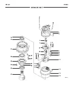
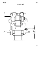
SWING DEVICE
Assemble Swing Motor
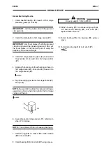
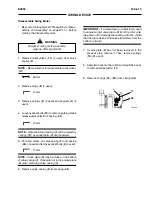
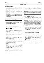
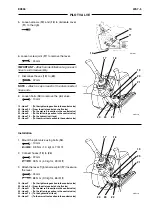
1. Install retaining ring (
47
) and spacer (
45
) onto
shaft (
37
).
Install the inner race of roller bearing (
39
) onto
shaft (
37
) using a press.
Install spacer (
45
) and retaining ring (
47
) onto
shaft (
37
).
2. Install the inner race of roller bearing (
1
) onto
shaft (
37
) using a press. Install retaining ring (
44
)
onto shaft (
37
).
IMPORTANT -
Be sure that the lip part of oil seal (
40
)
faces upwards when installing it.
3. Install oil seal (
40
) onto seal cover (
41
) using a
protection plate and a press.
4. Install the outer race of roller bearing (
39
) onto
casing (
43
) a metal bar and a hammer.
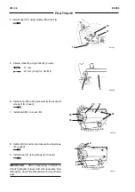
5. Lay casing (
43
) on its side. Install shaft (
37
) into
casing (
43
).
6. Stand casing (
43
) upright. Install O-ring (
48
) into
casing (
43
).
7. Install seal cover (
41
) into casing (
43
). Secure
with retaining ring (
42
).
8. Install spacer (
38
), spring (
30
), and spacer (
45
)
into rotor (
27
), in that order.
9. Press down spacer (
45
) to give enough clear-
ance for retaining ring (
31
) installation. Install
retaining ring (
31
).
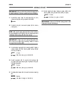
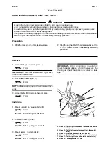
10. Insert push rods (
16
) (12 used) into rotor (
27
).
Install spacer (
17
) and holder (
18
) onto rotor (
27
),
in that order.
11. Attach plungers (
34
) (9 used) on retainer plate
(
35
). Insert plungers (
34
) into rotor (
27
).
IMPORTANT -
Be sure to apply a film of hydraulic
oil on the rotor bore surface before inserting plungers
(
34
).
12. Lay casing (
43
) on its side.
Install thrust plate (
36
) onto rotor (
27
). Install
them onto shaft (
37
).
IMPORTANT -
On each of plate (
32
) periphery is a
series of tab-like protrusions with four of the protru-
sions missing at an interval. Likewise, four teeth are
missing on each friction plate. When installing plates
(
32
) and friction plates (
13
), be sure to align these
missing parts.
13. Stand casing (
43
) upright. Install plates (
32
)
(3 used) and friction plates (
13
) (2 used) one by
one alternately.
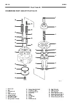
14. Install O-rings (
12
) and (
33
) on casing (
43
).
15. Install brake piston (
11
) into casing (
43
). If brake
piston (
11
) does not enter the casing smoothly
due to the installation of the O-rings above, tap
the periphery of the brake piston evenly with a
plastic hammer.
16. Install spring (
10
) (24 used ) on brake piston (
11
).
Summary of Contents for EX355 Tier2
Page 22: ...T1 2 10 EX355 COMPONENT LAYOUT NOTES ...
Page 37: ...T2 1 14 EX355 CONTROL SYSTEM NOTES ...
Page 47: ...T2 2 10 EX355 HYDRAULIC SYSTEM NOTES ...
Page 73: ...T2 3 26 EX355 ELECTRICAL SYSTEM NOTES ...
Page 86: ...T3 1 12 EX355 PUMP DEVICE NOTES ...
Page 94: ...T3 2 8 EX355 SWING DEVICE NOTES ...
Page 134: ...T3 4 10 EX355 PILOT VALVE NOTES ...
Page 146: ...T3 5 12 EX355 TRAVEL DEVICE NOTES ...
Page 156: ...T3 7 4 EX355 OTHER COMPONENTS Undercarriage NOTES ...
Page 195: ...T4 2 6 EX355 STANDARD NOTES ...
Page 199: ...T4 3 4 EX355 ENGINE TEST NOTES ...
Page 215: ...T4 4 16 EX355 EXCAVATOR TEST NOTES ...
Page 237: ...T4 5 22 EX355 COMPONENT TEST NOTES ...
Page 265: ...T5 2 12 EX355 COMPONENT LAYOUT NOTES ...
Page 325: ...T5 4 52 EX355 TROUBLESHOOTING B ...
Page 372: ...EX355 T5 6 9 ELECTRICAL SYSTEM INSPECTION ...
Page 385: ...T5 6 22 EX355 ELECTRICAL SYSTEM INSPECTION NOTE ...
Page 425: ...W1 1 4 EX355 PRECAUTIONS FOR DISASSEMBLY AND ASSEMBLY NOTES ...
Page 450: ...W2 3 8 EX355 MAIN FRAME NOTES ...
Page 454: ...W2 4 4 EX355 PUMP DEVICE SM5510 ...
Page 456: ...W2 4 6 EX355 PUMP DEVICE SM5510 ...
Page 458: ...W2 4 8 EX355 PUMP DEVICE ASSEMBLE PUMP DEVICE SM6205 SM6206 ...
Page 460: ...W2 4 10 EX355 PUMP DEVICE SM6205 SM6206 ...
Page 462: ...W2 4 12 EX355 PUMP DEVICE SM6205 SM6206 ...
Page 464: ...W2 4 14 EX355 PUMP DEVICE SM6205 SM6206 ...
Page 468: ...W2 4 18 EX355 PUMP DEVICE SM6210 ...
Page 470: ...W2 4 20 EX355 PUMP DEVICE SM6210 ...
Page 472: ...W2 4 22 EX355 PUMP DEVICE SM6210 ...
Page 474: ...W2 4 24 EX355 PUMP DEVICE SM5511 SM6219 ASSEMBLE MAIN PUMP ...
Page 476: ...W2 4 26 EX355 PUMP DEVICE SM5511 SM6219 ...
Page 478: ...W2 4 28 EX355 PUMP DEVICE SM5511 SM6219 ...
Page 480: ...W2 4 30 EX355 PUMP DEVICE SM5511 SM6219 ...
Page 482: ...W2 4 32 EX355 PUMP DEVICE SM5511 SM6219 ...
Page 484: ...W2 4 34 EX355 PUMP DEVICE SM5511 SM6219 ...
Page 486: ...W2 4 36 EX355 PUMP DEVICE SM5511 SM6219 ...
Page 498: ...W2 4 48 EX355 PUMP DEVICE NOTES ...
Page 532: ...W2 5 34 EX355 CONTROL VALVE NOTES ...
Page 540: ...W2 6 8 EX355 SWING DEVICE SM6277 31 18 17 20 19 21 3 24 27 25 26 10 ...
Page 542: ...W2 6 10 EX355 SWING DEVICE SM6277 31 19 2 1 23 22 ...
Page 566: ...W2 7 12 EX355 PILOT VALVE 11 19 17 18 1 2 3 8 13 14 16 15 SM1114 ...
Page 572: ...W2 7 18 EX355 PILOT VALVE 8 6 7 1 3 4 5 9 21 2 SM1119 ...
Page 586: ...W2 7 32 EX355 PILOT VALVE NOTES ...
Page 592: ...W2 8 6 EX355 PILOT SHUT OFF VALVE NOTES ...
Page 602: ...W2 10 6 EX355 SOLENOID VALVE UNIT NOTES ...
Page 621: ...W3 2 10 EX355 TRAVEL DEVICE SM5108 44 8 13 12 1 45 46 28 27 25 26 24 36 38 30 31 32 ...
Page 627: ...W3 2 16 EX355 TRAVEL DEVICE SM5502 3 4 5 20 7 8 9 10 12 14 13 16 11 6 ...
Page 643: ...W3 2 32 EX355 TRAVEL DEVICE NOTES ...
Page 651: ...W3 3 8 EX355 CENTER JOINT NOTES ...
Page 655: ...W3 4 4 EX355 TRACK ADJUSTER 8 14 13 11 17 12 SM6284 ...
Page 657: ...W3 4 6 EX355 TRACK ADJUSTER 3 4 8 10 16 15 14 SM6284 ...
Page 659: ...W3 4 8 EX355 TRACK ADJUSTER 3 6 4 8 10 9 SM6284 18 ...
Page 667: ...W3 4 16 EX355 TRACK ADJUSTER NOTES ...
Page 671: ...W3 5 4 EX355 FRONT IDLER 1 SM6290 2 4 3 5 6 8 12 7 6 3 4 1 2 9 10 11 ...
Page 689: ...W3 6 14 EX355 UPPER AND LOWER ROLLER NOTES ...
Page 708: ...W4 1 10 EX355 FRONT ATTACHMENT NOTES ...
Page 716: ...W4 1 18 EX355 FRONT ATTACHMENT NOTES ...
Page 744: ...W4 2 28 EX355 CYLINDERS NOTES ...
Page 763: ...EX355 W5 1 17 GENERAL INFORMATION Oil Pan N m kgf m Ib ft SM7010 ...
Page 765: ...EX355 W5 1 19 GENERAL INFORMATION Water Pump N m kgf m Ib ft SM7012 ...
Page 815: ...EX355 W5 3 35 ENGINE OVERHAUL Disassembly SM7093 1 Camshaft gear 2 Knock pin 3 Camshaft ...
Page 883: ...EX355 W5 3 103 ENGINE OVERHAUL Reassembly 1 Crankshaft 3 Crankshaft gear 2 Pin SM7239 ...
Page 894: ...W5 3 114 EX355 ENGINE OVERHAUL NOTE ...
Page 938: ...W5 7 6 EX355 ENGINE INDUCTION NOTE ...


