background image

4 Product Installation

4.

Observe the LINK indicator LED (the one on the left side of the
Ethernet interface). If the LINK indicator LED is ON or blinking,
the network cable is correctly connected; otherwise, check the
connection of the network cable.

5.

During the equipment running, ensure that it is correctly
grounded to avoid failure. If any failure occurs, please contact
the local office of FiberHome.

48

Summary of Contents for AN5121-4GP

Page 1: ...An Expert in Optical Communications User Manual AN5121 4GP PON Optical Network Unit Version A Code MN000001901 Date September 2014 FiberHome Telecommunication Technologies Co Ltd...

Page 2: ...d in this document are used for identification purposes only and are trademarks or registered trademarks of their respective holders All rights redserved No part of this document including the electro...

Page 3: ...the Waterproof Shell 15 3 3 2 Interface of the Equipment 15 3 3 3 Introduction to the Pole Components 17 3 3 4 Introduction to the Cabinet Components 18 4 Product Installation 19 4 1 Installation Prep...

Page 4: ...t 41 4 4 4 Connecting Wires and Cables 42 4 5 Cabinet Mounting Mode 42 4 5 1 Installation Flow Chart 42 4 5 2 Installing the Mounting Ears 43 4 5 3 Cabinet Mounting Mode 44 4 5 4 Connecting Wires and...

Page 5: ...ric cable immediately When inserting the power connector of the device into an external power socket make sure that the external power socket is close enough to the device for easy operation If the po...

Page 6: ...1 Safety Precautions Install the silicon rubber waterproof band into the recess on the lower cover of the device case to ensure water proofing 2...

Page 7: ...sion distance can reach 20 km so as to deploy the equipment conveniently Its four GE interfaces can act as the data and power supply interfaces at the same time so as to provide the power supply and d...

Page 8: ...ode selection The Ethernet interface can work under the 10 100 1000 Mbit s full duplex half duplex status in the auto negotiation or the forced mode 4 Supports the LAN port based rate control function...

Page 9: ...control functions 4 Supports the DHCP line label function 4 Supports the PPPoE function used to identify users exactly 4 Supports the DHCPv6 protocol without the status information and the PPPoEv6 pro...

Page 10: ...rd and the maximum power of the integrated equipment is 120 W 4 Supports the automatic manual feed mode 4 Supports querying the feed status of a port Product Model AN5121 4GP with four GE interfaces 2...

Page 11: ...l Specifications The technical specifications of the AN5121 4GP are listed in Table 2 1 Table 2 1 The AN5121 4GP Technical Specifications Type Item Description Service parameters VLAN Supports the IEE...

Page 12: ...s available which meets the ITU T G 984 standard User side interface GE interface Four GE interfaces are available whose type is RJ 45 They support 10 100 1000 Mbit s full duplex half duplex adaptatio...

Page 13: ...echnical Specifications Continued Type Item Description Power consump tion parameters Full load 130W Empty load 10W Environ ment parameters Operating temperature 30 to 55 Storage temperature 55 to 125...

Page 14: ...ollowing introduces the appearance of the AN5121 4GP and the waterproof shell for it The AN5121 4GP The overall appearance of the AN5121 4GP is shown in Figure 3 1 Figure 3 1 The Appearance of the AN5...

Page 15: ...op internal side is equipped with the waterproof bumper case which can prevent the rain from entering the shell via the gaps The appearance of the waterproof shell is shown in Figure 3 3 1 Lock 2 LOGO...

Page 16: ...3 Product Appearance 1 Wiring hole optional 2 Earth ground component optional 3 Cable fixing component optional Figure 3 4 Internal Structure of the Waterproof Shell 12...

Page 17: ...de the shell 1 Cable fixing component optional For securing multiple network cables from the AN5121 4GP to the external 1 3 2 Indicator LED Description The AN5121 4GP has multiple types of indicator L...

Page 18: ...status indicator LED left Orange ON A certain equipment set is connected to the LAN port without data transmission Blinking A certain equipment set is connected to the LAN port with data transmission...

Page 19: ...ription 1 Wiring hole for the earth ground cable Wiring hole for the power cable Wiring hole for the optical cable The earth ground cable the power cable and the optical cable are led into the waterpr...

Page 20: ...und cable interface Used for the earth grounding of the equipment Power switch Used to switch on or off the AN5121 4GP AC power interface Used to induct the 220 V AC power supply from the external GPO...

Page 21: ...Pole Components The pole components comprise the equipment base and clamp The clamp is used to secure the equipment base on the wire pole Figure 3 7 shows the equipment base Figure 3 7 The Base Figur...

Page 22: ...ts The cabinet components include the two mounting ears used to secure the equipment in the cabinet as shown in Figure 3 9 and Figure 3 10 Figure 3 9 The Mounting Ear on the Left Side of the Cabinet F...

Page 23: ...1 4GP For example check whether the power cables and optical cables can be accessed u The installation position provides good conditions for grounding of the workbench wall poles and cabinet u The wor...

Page 24: ...4 Product Installation 4 3 Pole holding Mounting Mode 4 3 1 Installation Flow Chart The installation flow chart for the pole holding mode is shown in Figure 4 1 20...

Page 25: ...Product Installation Figure 4 1 The Installation Flow Chart for the Pole holding Mounting Mode 4 3 2 Pole Mounting Mode The following introduces how to secure the waterproof shell on the wire pole 21...

Page 26: ...the equipment base and the clamp Figure 4 2 shows the base and Figure 4 3 shows the clamp Figure 4 2 The Base Figure 4 3 The Clamp 2 Secure the equipment base onto the wire pole with the clamp as show...

Page 27: ...wn in Figure 4 5 1 Find the hooks on the back of the waterproof shell as indicated by 1 of Figure 4 5 and the gourd shaped holes on the equipment base as indicated by 2 of Figure 4 5 2 Align the hooks...

Page 28: ...5 Hanging the Waterproof Shell 4 3 3 Securing the Equipment Tool None Procedure Secure the AN5121 4GP in the waterproof shell as illustrated in Figure 4 7 1 Find the mounting holes at the bottom of t...

Page 29: ...with the equipment to the bottom of the equipment as illustrated in Figure 4 6 Figure 4 6 Installing the Sheet Metal 3 Align the mounting holes at the bottom of the AN5121 4GP with the hooks inside t...

Page 30: ...Installation 1 Mounting hole 2 Hook Figure 4 7 Securing the Equipment to the Waterproof Shell 4 3 4 Connecting Wires and Cables The following introduces how to connect the wires and cables for the equ...

Page 31: ...used to connect the equipment and the external earth ground bar The equipment earth ground cables comprise the external earth ground cable and the internal earth ground cable Tool A cross screwdriver...

Page 32: ...4 Connect the other end of the external earth ground cable to the external earth ground bar 5 Fix one end of the internal earth ground cable on the earth ground point of the earth ground component as...

Page 33: ...Product Installation Figure 4 9 Connection to the Earth Ground Point 6 Insert the other end of the internal earth ground cable into the earth ground hole of the AN5121 4GP as shown in of Figure 4 10 2...

Page 34: ...on 1 Waterproof connector 2 Connector post 3 Earth ground point Figure 4 10 Connecting the Earth Ground Cable 4 3 4 2 Connecting the Power Cable The power cable is used to connect the external power a...

Page 35: ...on the left side of the waterproof shell 2 Lead one end of the power cable into the equipment via the wiring hole on the left side of the waterproof shell as shown in of Figure 4 11 3 Connect the int...

Page 36: ...4 Product Installation 1 Waterproof connector Figure 4 11 Connecting the Power Cable 32...

Page 37: ...interface and the external communication equipment Tool Cutting pliers Procedure 1 Loosen the waterproof connector on the wiring hole on the left side of the waterproof shell 2 Lead one end of the opt...

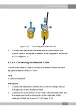
Page 38: ...tor Figure 4 12 Connecting the Optical Cable 3 Install the connector for the optical fiber of the optical cable entering the equipment 4 Connect the reinforced core of the optical cable to the earth g...

Page 39: ...necting the Network Cable The network cable is used to connect the external communication equipment and the AN5121 4GP Tool A cross screwdriver Procedure 1 Loosen the waterproof connectors on the two...

Page 40: ...4 Product Installation 1 Waterproof connector 2 Cable fixing component Figure 4 14 Connecting the Network Cable 3 Lead the network cable through the cable fixing component 36...

Page 41: ...e RJ 45 connector of the network cable into the AN5121 4GP s network interface as shown in of Figure 4 14 4 4 Wall Mounting Mode 4 4 1 Installation Flow Chart The installation flow for the wall mounti...

Page 42: ...4 Product Installation Figure 4 15 The Installation Flow Chart for the Wall Mounting Mode 4 4 2 Wall Mounting Mode The following introduces how to mount the waterproof shell on the wall 38...

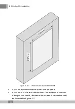
Page 43: ...ion Tool u An electric drill u A hammer u A cross screwdriver Procedure 1 Take out the waterproof shell 2 Drill four holes on the wall with the electric drill See Figure 4 16 for the positions and siz...

Page 44: ...s and Sizes of the Holes 3 Install the expansion sleeve in the holes prepared 4 Install the four screws on the bottom of the waterproof shell into the expansion sleeve and fasten the screws to secure...

Page 45: ...llation 1 Screw 2 Expansion sleeve Figure 4 17 Securing the Waterproof Shell 4 4 3 Securing the Equipment Secure the AN5121 4GP in the waterproof shell Refer to Securing the Equipment for the operatio...

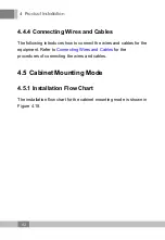
Page 46: ...w to connect the wires and cables for the equipment Refer to Connecting Wires and Cables for the procedures of connecting the wires and cables 4 5 Cabinet Mounting Mode 4 5 1 Installation Flow Chart T...

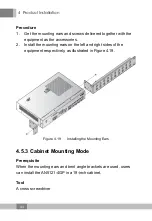
Page 47: ...llation Figure 4 18 The Installation Flow Chart for the Cabinet Mounting Mode 4 5 2 Installing the Mounting Ears The following introduces how to install the mounting ears on the equipment Tool A cross...

Page 48: ...tall the mounting ears on the left and right sides of the equipment respectively as illustrated in Figure 4 19 Figure 4 19 Installing the Mounting Ears 4 5 3 Cabinet Mounting Mode Prerequisite When th...

Page 49: ...mounting ears and bent angle brackets on both sides of the AN5121 4GP Push the mounting ears and bent angle brackets slowly toward the floating nuts until they touch closely Then insert the screws in...

Page 50: ...abinet 4 5 4 Connecting Wires and Cables The following introduces how to connect the wires and cables for the equipment The wires and cables to be connected for the equipment include u The earth groun...

Page 51: ...etwork cable from the external into the cabinet and insert the network plug into the network interface 4 6 Post installation Inspection After all cables are connected and related services are requeste...

Page 52: ...terface If the LINK indicator LED is ON or blinking the network cable is correctly connected otherwise check the connection of the network cable 5 During the equipment running ensure that it is correc...

Page 53: ...cable FAQ2 The equipment stops running after normal operation for a period of time 1 Check whether the power cable terminal has a poor contact 2 Check whether the power voltage is excessively high or...

Page 54: ...No 6 network cables are 0V ones 4 Check whether the PD is faulty 5 Check whether the ONU equipment is operating normally FAQ5 When the Ethernet wiring outlet port is connected to the client side PD P...

Page 55: ...the date of purchase The original dated bill of sale should be retained as proof of purchase and must be presented to FiberHome when the equipment is to be serviced under the provisions of this warra...

Page 56: ...by transporting loading and unloading 2 Damage or malfunction caused by man made reasons such as opening or remodel the machine on users own 3 Damage or malfunction caused by unsatisfactory environme...

Page 57: ...product documentation 1 How often do you use the documentation Frequently Rarely Never Other please specify 2 When do you use the documentation in starting up a project in installing the product in d...

Page 58: ...tisfied with Why 9 What is your opinion on the Figures in the documentation Beautiful Unbeautiful your advice Practical Unpractical your advice 10 What is your opinion on the layout of the documentati...

Page 59: ......

Page 60: ...FiberHome Telecommunication Technologies Co Ltd Address No 67 Guanggu Chuangye Street Wuhan Hubei China Zip code 430073 Website www fiberhomegroup com...

Reviews: