2 Equipment Housing Description
9
2.3 Interface and Button Description
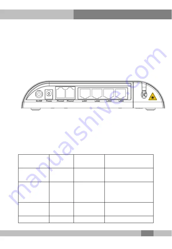
With all interfaces and buttons distributed on the rear panel, the
AN5506-04-B has a simple model and is convenient for use. As
shown in Figure 2.2, the interfaces and buttons from left to right are:
power switch, power interface, telephone interfaces (
×
2), Ethernet
interfaces (
×
4) and PON interface.
Figure 2.2
Front view of the AN5506-04-B rear panel
The interface and button distribution of the AN5506-04-B facilitates
the cable and wire connection. See Table 2.2 for the interface and
button description.
Table 2.2 Description for the AN5506-04-B interfaces and buttons
Button /
Interface
Meaning Type
Description
On/Off
Power
switch
Button
Turns on or off the power.
DC 12V
Power
interface
3-conductor
power
interface
Connects to the DC
power adapter.
Phone1 to
Phone2
Telephone
interface
RJ-11
Connects to the user’s
telephone.
LAN 1 to LAN Ethernet
RJ-45
Connects to the user’s


