background image

HG6543C Product Manual

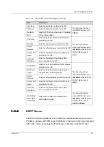
Table 3-5

Parameters of LAN Settings (Continued)

Item

Description

DNS Source

The source of the DNS distributed to the PC. The options include

WAN connection, ONT proxy and static configuration. The default

setting is WAN connection.

Prefix Mode

The source of the prefix information distributed to the PC. The options

include WAN connection and static configuration. The default setting

is WAN connection.

Enable DHCP6S

Sets whether to enable the DHCPv6 server. This item should be

selected if

Managed Flag

or

Other Config Flag

is selected;

otherwise the IP address or DNS information cannot be distributed.

The server is enabled by default.

Start IPv6 Address

The starting address ID of the address pool for distribution of DHCPv6

IP addresses. The default value is 0:0:0:2.

End IPv6 Address

The ending address ID of the address pool for distribution of DHCPv6

IP addresses. The default value is 0:0:0:255.

3.3.3

3.3.3

Broadband Settings

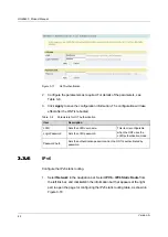
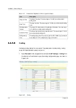
Select the WAN connection suitable for the network environment, or configure the

parameters concerned for the selected WAN connection.

1.

Select

Network

in the navigation bar and select

BroadBand Settings

Internet Settings

in the left link bar to open the Internet settings page, as

shown in Figure 3-15.

36

Version: A

Summary of Contents for HG6543C

Page 1: ...HG6543C Product Manual Version A FiberHome Telecommunication Technologies Co Ltd July 2019...

Page 2: ......

Page 3: ...ocal sales representative service representative or distributor for any help needed at the contact information shown below Fiberhome Telecommunication Technologies Co Ltd Address No 67 Guanggu Chuangy...

Page 4: ......

Page 5: ...nt are used for identification purposes only and are trademarks or registered trademarks of their respective holders All rights reserved No part of this document including the electronic version may b...

Page 6: ......

Page 7: ...ediately u Use the power supply adapter provided in the package only Using other adapters may cause equipment damage or operation failures u Install the equipment in a well ventilated environment with...

Page 8: ......

Page 9: ...oduction to the HG6543C 6 2 4 1 Appearance 6 2 4 2 Product Characteristics 10 2 4 3 Functions and Features 12 2 4 4 Technical Specifications 16 3 Web Configuration Guide 17 3 1 Local Login to the Web...

Page 10: ...3 6 1 User Management 74 3 6 2 Device Management 76 3 6 3 Log Management 80 4 Handling Common Problems 82 4 1 Power Status Indicator LED Extinguished 83 4 2 Register Status Indicator LED Extinguished...

Page 11: ...4 10 Test of Voice Service Failed 85 5 Standards and Protocols 86 Appendix A Abbreviations 88...

Page 12: ......

Page 13: ...ormation A Initial version Content Chapter Summary Product Introduction u Product Positioning u Product Specification u Interface Specifications u Introduction to the HG6543C Web Configuration Guide u...

Page 14: ...2 2 Product Introduction Product Positioning Product Specification Interface Specifications Introduction to the HG6543C 2 Version A...

Page 15: ...ses The figure below shows the network positioning of the HG6543C 2 2 2 2 Product Specification The tables below describe the interfaces and services supported by the HG6543C which can be referred to...

Page 16: ...tem Specification Standard compliance ITU T G 984 Class B Transmission rate Rx 2 5 Gbit s Tx 1 25 Gbit s Interface mode Single mode Interface type SC UPC or SC APC Maximum transmission distance 20 km...

Page 17: ...s Cable type Twisted pair cable Line code PCM 2 3 4 2 3 4 Wi Fi Interface Item Specification Standard compliance IEEE 802 11 b g n Operating band 2 4GHz Specifications Four SSIDs and 13 working channe...

Page 18: ...This section describes the appearance of the HG6543C including the overall look interfaces buttons and indicator LEDs Note The pictures here are only for reference Appearance The overall look of the...

Page 19: ...nterfaces and buttons of the HG6543C are located on the rear side and bottom panels of the equipment Figure 2 2 Figure 2 3 and Figure 2 4 show the rear panel side panel and bottom panel respectively F...

Page 20: ...HG6543C Product Manual Figure 2 3 Side Panel of the HG6543C Figure 2 4 Bottom Panel of the HG6543C Table 2 3 describes the interfaces and buttons on the HG6543C 8 Version A...

Page 21: ...LAN function WPS WPS function button Enables disables WLAN data encryption PON Fiber interface Connects with the optical fiber for uplink access Indicator LEDs Indicator LEDs of the HG6543C are locate...

Page 22: ...nabled or the Wi Fi terminal is not connected to the ONT USB USB indicator LED Green ON The USB is connected OFF The USB is not connected LAN1 to LAN4 Ethernet interface status indicator LED Green ON...

Page 23: ...b g n and authenticated by Wi Fi Alliance with good compatibility with other WLAN devices u Supports four SSIDs so that users can set different wireless networks as needed u Supports multiple authent...

Page 24: ...time monitoring of the network performance u Supports remote fault isolation for the ONT via the network management system Faults can be isolated remotely according to the alarms reported to reduce t...

Page 25: ...Supports generation of the key and response to the OLT s request for key Supports OMCI channel encryption Registration authentication Supports the ONT registration process as specified in ITU T G 984...

Page 26: ...fferent GEM ports Supports configuration of the multicast GEM ports Supports authentication of the GEM ports Supports no less than 256 multicast groups Supports the IPoE PPPoE mode for multicast servi...

Page 27: ...ency band Supports automatic selection and manual configuration of channels Supports Open System Shared key WPA PSK WPA2 PSK and WPA PSK WPA2 PSK authentication Supports the WEP TKIP AES and TKIP AES...

Page 28: ...2 1p values of packets Supports the ACL function to match traffics based on the ACL rules Supports three queue scheduling modes PQ WRR and PQ WRR supports configuring the weight of scheduled queues to...

Page 29: ...including the parameter meanings and operation methods Note Configure the ONTon the OLT via the access network management system For details please refer to the relevant OLTconfiguration guide Local L...

Page 30: ...on GUI Prerequisites u The ONT has been connected to the computer correctly u The user computer is started normally u The ONT is started normally Press down the ONT s power button If the power indicat...

Page 31: ...address and subnet mask of the ONT Factory default value u IP address 192 168 1 1 u Subnet mask 255 255 255 0 Note Some operators require customized management IP address so that the default manageme...

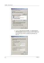
Page 32: ...the Local Area Connection Status dialog box and click Properties c In the Local Area Connection Properties dialog box that appears double click Internet Protocol 4 TCP IPv4 d In the Internet Protocol...

Page 33: ...operating system are as follows a In the Windows taskbar select Start Control Panel Double click Network Connection to access the network connection window b Right click Local Connection and select Pr...

Page 34: ...ual c Double click Internet Protocol TCP IP In the Internet Protocol TCP IP Properties dialog box that appears set the IP address and subnet mask of the computer For details of the parameters see Tabl...

Page 35: ...system will log out automatically if no user operation is detected in five minutes Layout of the Web Configuration GUI The Web configuration GUI comprises three parts as shown in Figure 3 1 u Navigat...

Page 36: ...iguration items please refer to the practical GUIs 4 The Status tab 4 Wlan Settings in the Network tab 4 User Account and Device Reboot in the Management tab 3 2 3 2 Status This section introduces how...

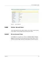
Page 37: ...equency channel SSID count of wireless packets and list of Wi Fi clients 3 2 2 1 3 2 2 1 Wireless Network Status Select Status in the navigation bar and then select Wireless Status Wireless Status in...

Page 38: ...bar to view the list of client ends connected to the ONT wireless network as shown in Figure 3 4 Figure 3 4 WIFI User List 3 2 3 3 2 3 WAN Side Status Select Status in the navigation bar and then sel...

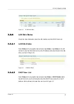
Page 39: ...Lan Status Lan Status in the left link bar to view the information such as the IP address and subnet mask of the LAN side as shown in Figure 3 6 Figure 3 6 LAN Side Status 3 2 4 2 3 2 4 2 DHCP User Li...

Page 40: ...al module information such as the Tx optical power Rx optical power and working temperature as shown in Figure 3 8 Figure 3 8 Optical Power Status 3 2 6 3 2 6 Voice Status Select Status in the navigat...

Page 41: ...Basic Parameters Configure the parameters of the 2 4G wireless network such as the switch network mode domain frequency bandwidth and frequency channel 1 Select Network in the navigation bar and sele...

Page 42: ...d The options include 20MHz 40MHz 20MHz and 40MHz Frequency Channel The channel used for communication between the wireless access point and the wireless station The options includes AutoSelect and Ch...

Page 43: ...ecurity cannot be guaranteed This mode is not advisable u SHARED This mode is based on the WEP encryption protocol where the same key is configured for the wireless access client end and equipment sid...

Page 44: ...e containing 10 to 26 characters Note Pressing the Apply button will validate a single SSID choice configuration item If you do not click Apply after modifying the SSID 1 setting the modification will...

Page 45: ...er of WIFI Connections The maximum number of client ends supported by the SSIDs 3 3 1 4 3 3 1 4 WPS Configuration WPS can automatically set the wireless network name SSID and wireless encryption key f...

Page 46: ...click Connect 4 Select Please turn on the button of the equipment and press down the WPS button on the ONT Then press down the WPS button or the WPS software key on the client end 4 Wait until the con...

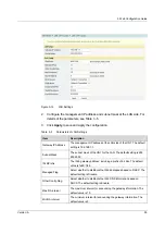
Page 47: ...mask of the ONT for the LAN The default setting is 255 255 255 0 IPv6 Prefix The IPv6 gateway address including a prefix of 64 bits The default value is fe80 1 64 Managed Flag Select whether to distr...

Page 48: ...Config Flag is selected otherwise the IP address or DNS information cannot be distributed The server is enabled by default Start IPv6 Address The starting address ID of the address pool for distributi...

Page 49: ...able for both TR069 and Internet access u VOIP this connection is only applicable for voice application u VOIP_INTERNET this connection is applicable for voice and Internet access u OTHER other connec...

Page 50: ...he default value LAN Binding Select the LAN port to be bound with the WAN port 2 4G SSID Binding Select the wireless 2 4G SSID to be bound with the WAN port IP Mode The options include IPv4 IPv6 IPv4...

Page 51: ...Pv6 Address Enter the static IPv6 address at the WAN side provided by the ISP This item should be set when the IP Mode is set to IPv4 IPv6 or IPv6 and the WAN IP Mode is set to static IPv6 Prefix Leng...

Page 52: ...rameters for the DHCP Server Item Description Type Enables or disables the DHCP server u Server Enables the DHCP server The ONTcan dynamically distribute IP addresses to user terminals u Disable The u...

Page 53: ...l Option 60 start IP The starting IP address of the network segment distributed to the Option 60 property terminal by the DHCP server This item should be configured when the Option 60 field of the DHC...

Page 54: ...LOID user name This item is configurable when the ONT uses the LOID authentication mode Logic Password Sets the LOID password Password Auth Sets the authentication password when the ONT is authenticat...

Page 55: ...next hop gateway WAN Name The WAN port passed by the static routing Select a valid WAN port 3 3 7 3 3 7 Voice Configuration This section introduces how to configure the key parameters basic parameters...

Page 56: ...eters for Voice Service Item Description VoIP Protocol The voice protocol type The options include SIP and H 248 The default setting is SIP Port Enable or disable the VoIP port 3 3 7 2 3 3 7 2 Basic P...

Page 57: ...ion Table 3 11 Basic Parameters for Voice Service Item Description VoIP Protocol The VoIP protocol type configured in Key Parameters VoIP Username The VoIP username VoIP Password The VoIP password Tel...

Page 58: ...CVLAN ID The value range is 1 to 4095 CVLAN Priority The CVLAN priority The value range is 0 to 7 and the default setting is 0 SVLAN ID The SVLAN ID The value range is 1 to 4095 SVLAN Priority The SVL...

Page 59: ...12 3 Click Apply to save and apply the configuration Table 3 12 Advanced Parameters for Voice Service Item Description RFC2833 PT Value The default PT value in RFC2833 The value range is 0 and 96 to...

Page 60: ...rt The value range is 1024 to 65535 and the default setting is 5060 Echo Cancel Enable or disable the echo suppression The default setting is Enable Silence Suppression Enable or disable the silence s...

Page 61: ...SIP registration period The value range is 120 to 65535 s and the default setting is 3600 Short Digit Timer The timeout period set for the short timer The value range is 1 to 254 s and the default se...

Page 62: ...is 30 Avalanche Timer The timeout period set for the avalanche timer The value range is 1 to 254 s and the default setting is 30 Sliding Spring Time The sliding spring time The value ranges from 90 t...

Page 63: ...n Period The RTP packetization period The value range is 10 to 60 ms 3 4 3 4 Security This section introduces how to configure the firewall remote control route QoS ACL configuration dynamic DoS and H...

Page 64: ...as required 3 Click Apply to save and apply the configuration 3 4 1 2 3 4 1 2 IPv4 Filtering Allow or forbid the incoming or outgoing flow of the IP packets meeting the filtering criteria After the fi...

Page 65: ...ltering rule table will be allowed to pass u Black List indicates that the data complying with the rules in the filtering rule table will not be allowed to pass Click the Apply button below to apply t...

Page 66: ...l is set to TCP or UDP Protocol The protocol type including TCP UDP ICMP and ALL 3 4 1 3 3 4 1 3 IPv6 Filtering Allow or forbid the IPv6 packets meeting the filtering criteria to be transmitted from t...

Page 67: ...ss Direction Sets the direction of the filtering rule u LAN WAN uplink direction u WAN LAN downlink direction Src IPv6 Enter the IPv6 address at the LAN side if the direction is set to LAN WAN Enter t...

Page 68: ...ng Parameters Item Description Enable Enables or disables the URL filtering function Click the Apply button below to apply the settings URL Blacklist Whitelist Select the filtering mode The white list...

Page 69: ...C address to obtain an IP address in the DHCP mode to prevent DOS attacks After the firewall is enabled the pre set rules will take effect 1 Select Security in the navigation bar and select Firewall D...

Page 70: ...obtain an IP address through the DHCP u Black List indicates forbidding the device configured with the MAC address to obtain an IP address through the DHCP MAC Address The MAC address of the user dev...

Page 71: ...Select Security in the navigation bar and select Firewall MAC Filtering in the left link bar and then click Add to open the MAC address filtering table configuration page as shown in Figure 3 30 Figu...

Page 72: ...Time The starting time of the filtering rule End Time The ending time of the filtering rule Enable Enables or disables this filtering rule The options include Disable and Enable 3 4 1 8 3 4 1 8 IPv6...

Page 73: ...Apply button below to apply the settings IPv6 MAC Filtering Blacklist Whitelist Select the filtering mode The white list and black list modes are configured globally and cannot be enabled simultaneou...

Page 74: ...addresses at the WAN side when enabled the PCs in the Internet can access the Web GUI of the ONT using the aforesaid IP addresses 1 Select Security in the navigation bar and select Remote Control Rem...

Page 75: ...lick Apply to save and apply the configuration 3 4 3 2 3 4 3 2 Route QoS Configuration While configuring the route QoS parameters you can classify the queues based on priority and process the messages...

Page 76: ...ocol types include ALL TCP and UDP Source IP The source IP address Source Port The source port Target IP The destination IP address Target Port The destination port Enable Enables or disables the QoS...

Page 77: ...nfiguration Table 3 22 Parameters for ACL Configuration Item Description ACL Enable Select to enable or disable the access control After setting click Submit at the upper right part to apply the setti...

Page 78: ...ences the handling of normal information flow The ONT provides the protection against the DoS attack 1 Select Security in the navigation bar and select DDOS DDOS in the left link bar to open the anti...

Page 79: ...3 Click Apply to save and apply the configuration 3 5 3 5 Application This section introduces how to configure the VPN DDNS port forwarding NAT UPnP DMZ and network diagnosis on the Web GUI 3 5 1 3 5...

Page 80: ...wn in Figure 3 40 Figure 3 40 DDNS Settings 2 Configure parameters relevant to DDNS according to the requirement For details of the parameters see Table 3 23 3 Click Apply to save and apply the config...

Page 81: ...ft link bar Then click Add to open the port forwarding configuration page as shown in Figure 3 41 Figure 3 41 Port Forwarding 2 Configure parameters relevant to port forwarding according to the requir...

Page 82: ...onversion between intranet IP addresses and public network IP addresses NATconverts a great number of intranet IP addresses into one or a small number of public network IP addresses so as to save the...

Page 83: ...blic network 3 5 5 3 5 5 UPnP Universal Plug and Play UPnP supports the plug and play function and the automatic discovery function for multiple network devices When the UPnP is enabled the devices su...

Page 84: ...rs according to the requirement For details of the parameters see Table 3 26 3 Click Apply to save and apply the configuration Table 3 26 Parameters for DMZ Configuration Item Description DMZ Enable E...

Page 85: ...open the network diagnosis page as shown in Figure 3 45 Figure 3 45 Network Diagnosis 2 Enter the destination IP address to be tested in the Destination Address box and click Ping or Traceroute to te...

Page 86: ...User management includes user account management and maintenance account management 3 6 1 1 3 6 1 1 User Account Management Users can add or delete a common user account or modify the password of a c...

Page 87: ...count Management Users can modify the username and password of the current account 1 Select Management in the navigation bar Select Account Management Maintenance Account from the left link bar to ope...

Page 88: ...nagement in the navigation bar Select Device Management Restore from the left link bar to open the configuration restoring page as shown in Figure 3 49 Figure 3 49 Restoring the Configuration Data 2 C...

Page 89: ...og box that appears select the device software version to be upgraded and click Open to upgrade the ONTsoftware 3 When the upgrade succeeds the page will prompt for device rebooting Click Reboot After...

Page 90: ...ame The FTP username Password The FTP password Localhost IP The local IP address File Name The existing file name of the ONT 3 6 2 5 3 6 2 5 FTP Server With the FTP server function of the ONTenabled u...

Page 91: ...in Figure 3 54 Figure 3 54 Device Reboot 2 Click Reboot and click OK in the alert box that appears and wait for the device to reboot Caution Save the configuration data before rebooting the device to...

Page 92: ...address of the active NTP server Second NTP Server Enter the IP address of the standby NTP server Time Zone Select the time zone according to the location of the device Current Time When NTP Check Tim...

Page 93: ...3 Web Configuration Guide Select Management in the navigation bar Select Log Log from the left link bar to open the log information page as shown in Figure 3 56 Figure 3 56 Log Version A 81...

Page 94: ...LED Extinguished Optical Signal Status Indicator LED Blinking Ethernet Interface Status Indicator LED Extinguished Failing to Detect the ONT Using Wi Fi Failing to Access Local Web Login GUI and Fail...

Page 95: ...connection is normal 3 Check whether the ONT has obtained the ISP authorization 4 Check whether the optical interface is normal if not replace the device 4 3 4 3 Optical Signal Status Indicator LED Bl...

Page 96: ...s terminal such as computer and telephone is enabled 3 Adjust the position of the ONT to reduce the barriers on the wireless channel such as walls and make sure the distance between the ONTand the wir...

Page 97: ...nternet Access Rate Out of Normal Range Contact the personnel in the network management center to check whether the bandwidth profile is configured correctly and bound to the ONT 4 10 4 10 Test of Voi...

Page 98: ...dged Local Area Networks Amendment 4 Provider Bridges IEEE 802 1ad IEEE Standard for Local and Metropolitan Area Networks Virtual Bridged Local Area Networks Amendment 4 Provider Bridges IEEE 802 1x 2...

Page 99: ...U T G 168 Digital network echo cancellers Multicast IETF RFC 2236 Internet Group Management Protocol Version 2 IETF RFC 3376 Internet Group Management Protocol Version 3 IETF RFC 4541 Considerations f...

Page 100: ...aintenance FEC Forward Error Correction TDMA Time Division Multiple Access PLOAM Physical Layer Operations Administration and Maintenance OMCI ONU Management and Control Interface T CONT Transmission...

Page 101: ...WLAN Wireless Local Area Networks MTU Maximum Transmission Unit PPPoE Point to Point Protocol over Ethernet DTMF Dual Tone Multi Frequency VPN Virtual Private Network DDNS Dynamic Domain Name Server F...

Page 102: ......

Page 103: ...en do you use the documentation Frequently Rarely Never Other please specify 2 When do you use the documentation in starting up a project in installing the product in daily maintenance in trouble shoo...

Page 104: ...inion on the Figures in the documentation Beautiful Unbeautiful your advice Practical Unpractical your advice 10 What is your opinion on the layout of the documentation Beautiful Unbeautiful your advi...

Reviews: