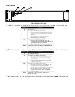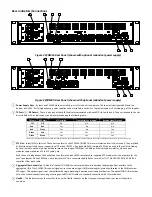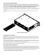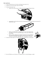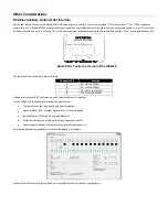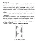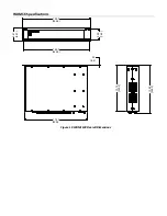
Introduction
The
FiberPlex
WDM
is
an
8
or
16
Channel
Wavelength
Division
Multiplexer,
with
each
optical
channel
brought
out
to
an
SFP
slot,
so
the
user
does
not
need
to
supply
wavelength
‐
specific
modules.
Each
channel
can
be
linked
via
fiber
with
selected
FiberPlex
FOM
or
FOI
fiber
modules,
FiberPlex
LightViper™
or
with
virtually
any
third
party
fiber
optic
equipment
with
data
rates
from
155
megabits
up
to
3
gigabits
per
channel,
for
a
possible
maximum
aggregate
data
rate
of
48
gigabits.
The
user
data
enters
and
leaves
the
WDM
via
16
SFP
slots
on
the
WDM16,
or
8
slots
on
the
WDM8A
and
WDM8B,
which
can
be
left
unpopulated
for
unused
channels,
or
populated
with
user
‐
supplied
MSA
‐
compliant
SFP
modules
that
are
appropriate
for
the
user’s
data
rate,
protocol
and
jitter
requirements.
Internally,
these
connect
to
fiber
optic
transceivers
which
are
tuned
to
the
specific
wavelengths
for
the
channels,
which
are
then
multiplexed
onto
the
aggregate
pair
which
connect
to
the
other
WDM(s)
in
the
link.
Data
that
enters
a
specific
channel
on
one
WDM
will
appear
on
the
corresponding
channel
on
the
other
WDM(s)
in
the
link,
with
no
interference
with
any
other
channels.
Possible
link
configurations
are:
WDM16
to
WDM16
–
all
16
channels
through
WDM8A
to
WDM8A
–
all
8
channels
through
WDM8B
to
WDM8B
–
all
8
channels
through
The
aggregate
fibers
from
the
WDM
units
exit
the
chassis
via
a
duplex
LC
coupler,
which
connect
to
single
mode
fiber,
up
to
20
km
in
length.
Since
this
is
an
aggregated
wideband
stream,
any
user
equipment
in
the
optical
path
(switches,
couplers,
etc.)
must
be
able
to
accommodate
the
entire
bandwidth
without
attenuation,
and
will
not
be
able
to
receive
or
decode
the
stream
digitally.
The
WDM
units
have
provision
for
two
(2)
power
supply
modules
for
redundancy
each
having
capacity
to
power
the
entire
unit.
An
AC
power
input
module
is
available
now
and
a
DC
version
is
in
development;
both
are
‘hot
swappable’.
Key
Features
16
(or
8)
Channel
Active
Wave
Division
Multiplexer
Combines
16
(or
8)
optical
channels
into
a
single
fiber
pair
Each
channel
independently
supports
data
rates
from
155
MB
up
to
3
GB
SMPTE
compatible
internal
fiber
optics,
video
optimized
to
support
Pathological
Signals
Each
optic
channel
can
independently
accept
multimode
or
single
mode
optics,
coax
connection
or
CAT5
using
flexible
SFP
modules
Fully
redundant,
hot
swappable
power
for
ultimate
reliability
WDM
Theory
of
Operation
Infrared
light
has
a
frequency
of
approximately
400
Terahertz
(400,000
Gigahertz).
That
is
about
125,000
times
higher
than
the
data
rate
of
a
typical
3
Gigabit
SFP,
which
means
a
large
proportion
of
the
bandwidth
of
a
fiber
optic
cable
is
wasted.
The
current
state
of
the
art
does
not
allow
utilizing
all
of
that
bandwidth,
but
we
can
recover
some
of
it
by
a
technique
called
“Coarse
Wave
Division
Multiplexing,”
or
“CWDM.”
Essentially,
it
is
the
simple
technique
of
taking
each
3
Gigabit
channel
and
using
it
to
modulate
a
different
frequency
in
that
400
Terahertz
bandwidth.
This
is
done
through
a
series
of
optical
filters
and
combiners,
along
with
lasers
and
photodiodes
tuned
to
a
particular
infrared
center
frequency.
Historically,
however,
optics
are
referred
to,
not
by
their
frequency,
but
by
their
wavelength,
which
is
the
speed
of
light
divided
by
the
frequency.
In
the
traditional
implementation
of
a
CWDM,
it
is
the
user’s
responsibility
to
provide
the
tailored
SFPs
and
the
CWDM
itself,
which
may
require
adapters
to
interface
with
the
user
equipment.
The
Fiberplex
WDM
line,
on
the
other
hand,
is
an
active
WDM,
with
the
wavelength
‐
specific
components
already
tested
and
configured.
Instead
of
a
wavelength
‐
specific
optical
fiber,
a
generic
SFP
electrical
interface
is
provided
for
each
channel.
Any
SFP
that
conforms
to
the
MSA
can
be
inserted,
even
copper
‐
based
SFPs
like
gigabit
Ethernet,
SDI,
HDMI
or
MADI.
The
internal
SFPs
have
a
full
3
Gigabit
bandwidth,
video
‐
optimized.
Generic
fiber
SFPs
have
limitations
in
passing
video
signals,
since
they
do
not
maintain
a
constant
DC
level.
The
video
‐
optimized
SFPs
are
constructed
to
better
handle
the
shifting
DC
levels
in
video
signals.
Summary of Contents for WDM16
Page 1: ...USER MANUAL Active Wave Division Multiplexer WDM16 WDM8A WDM8B...
Page 2: ......
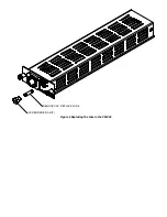
Page 13: ...REMOVE CAP REPLACE FUSE SCREWDRIVER SLOT Figure 6 Replacing the Fuse in the PSMAC...
Page 19: ......
Page 23: ......


