Power
Redundancy
In
order
to
remain
functional,
even
in
the
event
of
component
failures,
the
WDM
employs
the
following
redundancies:
Two
power
supply
slots,
with
load
equalizing
and
protection
circuitry
on
the
backplane.
Each
supply
has
thermal
and
overcurrent
protection.
Each
channel
has
its
own
independent
power
supply
that
runs
off
of
the
main
power
rails,
so
that
a
failure
in
one
channel
will
leave
the
others
operational.
There
is
a
microprocessor
in
the
unit,
but
its
function
is
purely
monitoring.
If
it
fails,
the
data
will
continue
to
flow
unimpeded
on
all
optical
channels.
There
are
two
independent
fan
control
channels,
and
two
cooling
fans
on
each
side
of
the
unit.
Differences
between
WDM16,
WDM8A
and
WDM8B
The
functional
and
physical
characteristics
of
the
WDM16,
WDM8A
and
WDM8B
are
largely
identical.
The
single
differentiator
is
the
number
of
Active
Wave
Division
channels
and
the
associated
internal
wavelengths
that
are
supported.
The
chassis
dimensions
and
power
supplies
remain
identical.
The
WDM16
supports
all
of
the
16
standard
CWDM
wavelengths
of
1310
‐
1610
nm,
whereas
the
WDM8
units
support
only
8
of
those
channels,
so
the
installation
can
be
scaled
to
the
appropriate
size.
The
WDM8A
supports
the
upper
8
wavelengths
1470
‐
1610
nm
and
the
WDM8B
supports
the
lower
8
wavelengths
1310
‐
1450
nm.
Because
of
the
enormously
flexible
active
nature
of
the
WDM16/8,
the
wavelengths
of
the
internal
channels
are
basically
invisible
and
even
irrelevant
to
the
end
user.
The
reasons
there
are
two
subsets
of
wavelengths
supported
through
the
WDM8A
and
WDM8B
is
for
future
expandability
of
the
line
in
providing
the
possibility
of
add/drop,
combining
and
splitting
capability.
When
only
8
channel
point
to
point
functionality
is
desired,
the
WDM8A
should
be
the
model
of
choice.
Model
Channels
Internal
Wavelengths
WDM16
16
1310
‐
1610
nm
WDM8A
8
1470
‐
1610
nm
WDM8B
8
1310
‐
1450
nm
Summary of Contents for WDM16
Page 1: ...USER MANUAL Active Wave Division Multiplexer WDM16 WDM8A WDM8B...
Page 2: ......
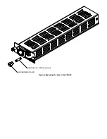
Page 13: ...REMOVE CAP REPLACE FUSE SCREWDRIVER SLOT Figure 6 Replacing the Fuse in the PSMAC...
Page 19: ......
Page 23: ......


