3 Application Interface
Copyright © Fibocom Wireless Inc.
40
3.6
Status Indicator
The FM101 module provides two signals to indicate the operating status of the module,
and the status indicator pins is shown in the following table:
Pin Pin Name
I/O Reset Value Pin Description
Level
10
LED1#
OD T
System status LED, drain output. 3.3V
23
WOWWAN#
DO
PD
Wake up host, default low,
Reserved
1.8V
3.6.1
LED#1 Signal
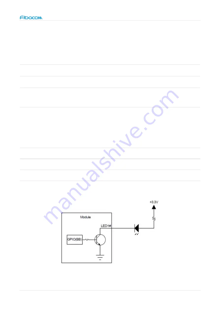
The LED#1 signal is used to indicate the operating status of the module, and the detailed
description is shown in the following table:
Module Status
LED1# Signal
RF function ON
Low level (LED on)
RF function OFF
High level (LED off)
The LED driving circuit is shown in figure 16:
Figure 16. LED driving circuit


