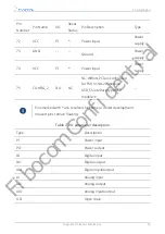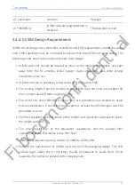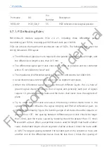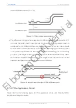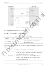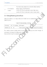
AT Command
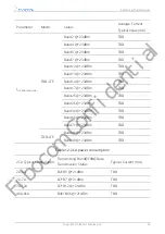
Function
Remark
AT+MSMPD=0
(U)SIM card hot plug detection is
disabled
Effective after restart
5.4.4. (U)SIM Design Requirements
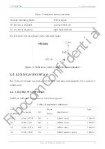
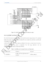
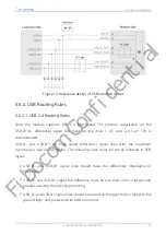
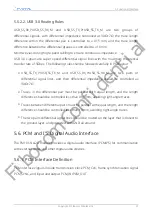
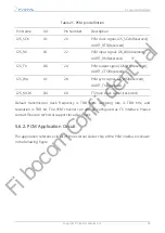
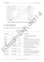
(U)SIM circuit design must meet EMC standards and ESD requirements, and at the same
time, EMS capability must be improved to ensure that the (U)SIM can work stably. The
following points need to be strictly observed in the design:
•
(U)SIM card slot should be located as close to the module as possible, and kept
away from the RF antenna, DCDC power, clock signal lines and other strong
interference sources.
•
(U)SIM card slot is covered by metal shield shell to improve EMS.
•
The routing length from the module to the (U)SIM card slot shall not exceed 100
mm. Longer cable will reduce signal quality.
•
The USIM_CLK and USIM_DATA signal lines are grounded and isolated to avoid
mutual interference. If conditions do not permit, at least the (U)SIM signal must be
grounded as a set.
•
The filter capacitor and ESD device of the (U)SIM card signal line are placed close to
the (U)SIM card slot.
•
The total capacitance of the equivalent capacitance and the parallel filter
capacitance of the ESD device is less than 47pF.
•
USIM_DATA requires a pull-up resistor of 20KΩ to USIM_VDD.
•
Refer to the specification of (U)SIM card slot for PCB packaging design. The PCB
surface layer under the 6 contactors should be keepout to avoid short circuit
caused by the contactor pricked to the copper plane.
5. Functional Interface
Copyright © Fibocom Wireless Inc.
34
Fibocom Confidential

