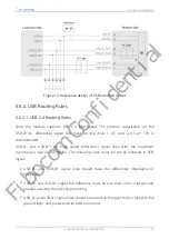
5.5.2.2. USB 3.0 Routing Rules
USB_SS_RX_P/USB_SS_RX_M and USB_SS_TX_P/USB_SS_TX_M are two groups of
differential signals, with differential impedance controlled at 90Ω±7Ω; the trace length
difference within the differential pair is controlled to
≤
0.15 mm, and the trace length
difference between the differential groups is controlled to
≤
10 mm.
Minimize vias during high-speed cabling to ensure continuous impedance.
USB 3.0 signals are super speed differential signal lines with the maximum theoretical
transfer rate of 5Gbps. The following rules shall be followed carefully in PCB layout:
•
USB_SS_TX_P/USB_SS_TX_M and USB_SS_RX_P/USB_SS_RX_M are two pairs of
differential signal lines, and their differential impedance should be controlled as
90
Ω
±7
Ω
.
•
Traces in the differential pair must be parallel with equal length, and the length
difference should be controlled less than 0.15 mm, avoiding right-angle traces.
•
Traces between differential pairs must be parallel with equal length, and the length
difference should be controlled less than 10 mm, avoiding right-angle traces.
•
The two pairs differential signal lines should be routed on the layer that is closest to
the ground layer, and protected with GND all around.
5.6. PCM and I
2
S Digital Audio Interface
The FM101-NA-20 module provides a digital audio interface (PCM/I
2
S) for communication
with external codec and other digital audio devices.
5.6.1. PCM Interface Definition
PCM interface signals include transmission clock PCM_CLK, frame synchronization signal
PCM_SYNC, and input and output PCM_IN/PCM_OUT.
5. Functional Interface
Copyright © Fibocom Wireless Inc.
37
Fibocom Confidential

