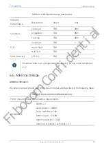
FM101-NA-20 module main antenna requirements
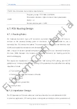
GNSS
Frequency range: 1559 MHz–1609 MHz
Polarization direction: right-circular or linear polarization
VSWR: < 2:1
Passive antenna gain: > 0dBi
6.7. PCB Routing Design
6.7.1. Routing Rules
For modules that don’t have a RF connector, customers need to route a RF trace to
connect to the antenna feeding point or connector. It is recommended to use a
microstrip line. The shorter the better. The insertion loss should be controlled less than
0.2dB; and impedance should be controlled within 50Ω.
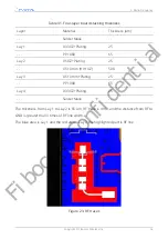
Add a π-type circuit (two parallel-component- grounded pins are connected directly to
the main GND) between the module and antenna connector (or feeding point) for
antenna debugging.
This signal line impedance is controlled within 50Ω during PCB cabling, and the RF
performance is closely related to this cabling. PCB parameters that will affect the cabling
impedance include:
•
Trace width and thickness
•
Dielectric constant and thickness of media
•
Thickness of pad
•
Distance from ground line
•
Nearby traces
6.7.2. Impedance Design
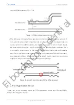
The RF impedance of the two antennas’ interface should to be controlled within 50Ω.
In practical application, RF routing mode is designed according to other parameters of
6. Radio Frequency
Copyright © Fibocom Wireless Inc.
50
Fibocom Confidential

