6.8.2. Internal Antenna
6.8.2.1. Design Principle of Internal Antenna
Placement
•
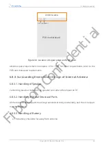
The antenna shall be arranged in the corners of the module.
•
Avoid placing metal elements near the antenna.
•
The shielding parts shall be as neat as possible. Do not use long strip shaped hole
slots.
•
Components with metal structure, such as horn, vibrator, and camera base plate
shall be grounded.
•
Avoid using long FPC. If a long FPC is required, add grounding shields on both
sides.
Routing
•
When connecting RF routing, apply circular arc treatment at the turning, take
grounding and pay attention to characteristic impedance.
•
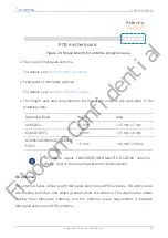
RF ground shall be designed properly, PCB board and edge of ground shall be
provided with "ground wall", and antenna led from RF module shall be made into
microstrip line.
•
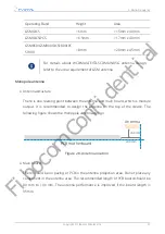
The antenna RF feeding point pad is a round rectangular pad with the size of 2 mm
×
3 mm. All layers of PCB that include the pad and surrounding and that are equal
to and greater than 0.8 mm are not covered with copper.
•
The center distance between RF and ground pad shall be between 4 mm and 5 mm.
6.8.2.2. Internal Antenna Classification
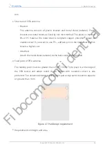
There are three kinds of internal antennas: PIFA, IFA and monopole. Internal antennas
may form interference and other potential problems in the product, so there are more
requirements in the design.
6. Radio Frequency
Copyright © Fibocom Wireless Inc.
54
Fibocom Confidential

