Reproduction forbidden without Fibocom Wireless Inc. written authorization - All Rights Reserved.
FM350-GL Hardware Guide
Page 35 of 59
configure the bands of LTE antenna to improve the antenna’s working efficiency and save space for the
antenna. Module also support 1.8V output for antenna tuner. The pin definition is as below table:
Pin
Pin Name
I/O
Pin Description
Level
24
ANT_TUNER_1V8
O
1.8V power output for antenna tuner, can mux as
GPIO.
Reserved
1.8V
56
RFFE_SCLK
O
Tunable ANT control, MIPI Interface,
RFFE clock
1.8V
58
RFFE_SDATA
I/O
Tunable ANT control, MIPI Interface,
RFFE data
1.8V
59
ANTCTL0
O
Tunable ANT control, GPO interface,
Bit0
1.8V
61
ANTCTL1
O
Tunable ANT control, GPO interface,
bit1
1.8V
63
ANTCTL2
O
Tunable ANT control, GPO interface,
Bit2
1.8V
65
ANTCTL3
O
Tunable ANT control, GPO interface,
Bit3
1.8V
3.9
Configuration Interface
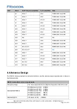
The FM350 module provides four pins for the configuration as the WWAN-PCIe, type M.2 module:
Pin
Pin Name
I/O
Reset Value
Pin Description
Level
1
CONFIG_3
O
-
NC
-
21
CONFIG_0
O
-
NC
-
69
CONFIG_1
O
L
Internally connected to GND
-
75
CONFIG_2
O
-
NC
-
The M.2 module configuration as the following table:
Config_0
(pin21)
Config_1
(pin69)
Config_2
(pin75)
Config_3
(pin1)
Module Type and
Main Host Interface
Port Configuration
NC
GND
NC
NC
WWAN
–PCIe Gen3, USB3.1
Gen1
Vendor defined
Please refer to PCI Express M.2 Specification Rev1.2” for more details.

