L831-EA Module Hardware User Manual
Page 37 of 43
1
CONFIG_3
O
Connect to GND within the module
0
21
CONFIG_0
O
NC
-
69
CONFIG_1
O
Connect to GND within the module
0
75
CONFIG_2
O
Connect to GND within the module
0
The configuration of M.2 Socket 2 Module as listed below :
Config_0
(pin21)
Config_1
(pin69)
Config_2
(pin75)
Config_3
(pin1)
Module Type and Main
Host Interface
Port Configuration
GND
GND
GND
GND
SSD-SATA
N/A
GND
GND
N/C
GND
WWAN-PCIe
N/A
GND
GND
GND
N/C
WWAN-USB3.0
0
5.15 RF Interface
5.15.1Description of RF Connector
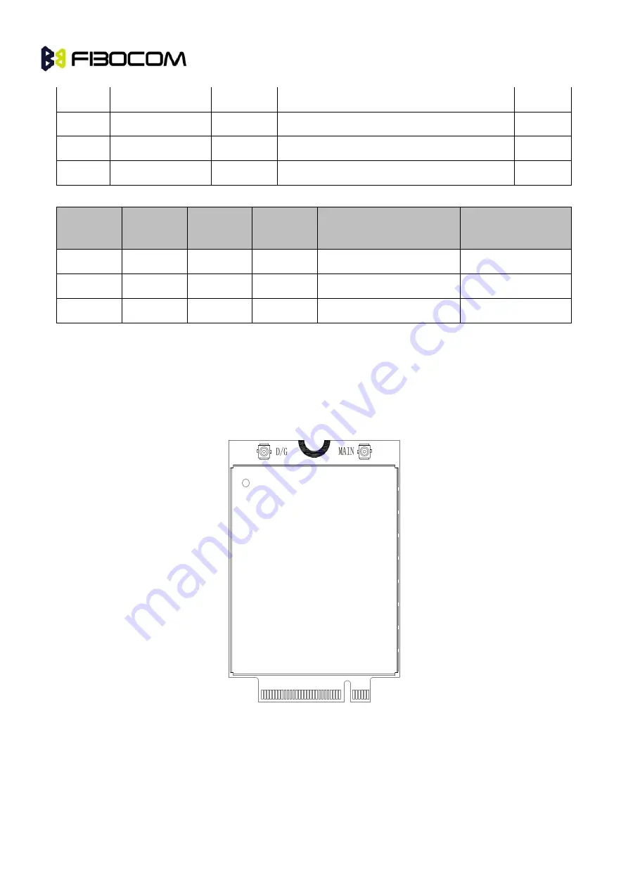
L831-EA module provides two RF connector for the connection of external antenna , the MAIN means the
main antenna of RF, and DIV means the diversity antenna .
Figure 5-9 RF connectors Diagram
5.15.2Description of RF Connecting Seat
L831-EA module adopts the RF connecting seat with Murata MM4829-2702, the size is 2*2*0.6mm, and
the structure diagram as follows:


