Reproduction forbidden without Fibocom Wireless Inc. written authorization - All rights reserved.
FIBOCOM MC610 Series Hardware Guide
16/70
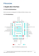
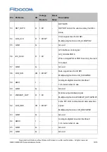
3.1.2 Pin Definition
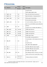
Table 3-1 Pin definition
Pin Pin Name
I/O
Voltage
Domain
Reset
Value
Description
1
GND
G
-
-
Ground
2
GND
G
-
-
Ground
3
ANT_MAIN
I/O -
-
Main set antenna
4
GND
G
-
-
Ground
5
GND
G
-
-
Ground
6
NC
-
-
-
-
7
GND
G
-
-
Ground
8
GND
G
-
-
Ground
9
VBAT
PI
Vmax=4.2V
Vmin=3.4V
Vnorm=3.8V
-
VBAT_GSM power input (3.4 to 4.2 V)
10
VBAT
PI
Vmax=4.2V
Vmin=3.4V
Vnorm=3.8V
-
VBAT_GSM power input (3.4 to 4.2 V)
11
USB_DM
I/O -
-
USB signal DM
12
USB_DP
I/O -
-
USB signal DP
13
VDD_IO
PO 1.8V
-
Module digital level, 1.8 V output
14
PWRKEY
I
VBAT
-
Module on/off, low level valid
15
SIM2_SIO
I/O 1.8V/3.0V
-
USIM2 data signal line
Support function GPIO30/SIM2_SIO/U1CTS
16
SIM2_SCLK
O
1.8V/3.0V
-
USIM clock signal line
Support function GPIO29/SIM2_SCLK
17
SIM2_SRST
O
1.8V/3.0V
-
USIM reset signal line


