Reproduction forbidden without Fibocom Wireless Inc. written authorization - All Rights Reserved.
FIBOCOM SU806 Series Hardware Guide
Page 62 of 91
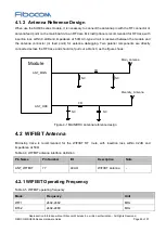
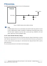
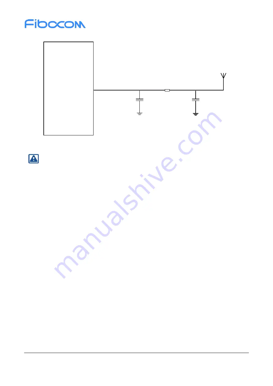
The GNSS antenna reference design is shown in the following figure:
Module
ANT_GNSS
GNSS_Antenna
NC
0R
82nH
Figure 4-3 GNSS passive antenna reference design
Note
:
For GNSS passive antenna, it is recommended to add an 82nH indictor near antenna connector
to improve GNSS antenna’s ability of resist ESD. For better ability of resist ESD, please choose
TVS that junction capacitance less than 0.5pF, recommended type: ESD9D5U, with 0.5pF
junction capacitance and 5.0V embedded voltage.
4.3.2.2 Active Antenna Reference Design
The power of the active antenna is fed from the antenna's signal line through a 56nH inductor. Common
active antennas supply power from 3.3V to 5.0V. The active antenna itself consumes very little power, but
requires a stable and clean power supply. It is recommended that a high-performance LDO be used to
power the antenna.
The active antenna reference circuit is shown in the following figure:


