4/8/16E1 Multiplexer User Manual V2.1
Beijing Fibridge Co., Ltd.
Tel: +8610-58858988 Fax: +8610-58858520 http://www.fibridge.com
- 28 -
6. Installation & Maintenance
6.1. Install the Module and Chassis
z
Open the package, check the device and the attachment,
contradistinguish to the Packing List;
z
Install the Module, such as EOW, POW, Multi-service
Multiplexer Module, to the Chassis;
z
Connect the ports to other proper device. For example,
connect the management port to the PC or the switch, connect
the E1 port to PBX, etc.
z
Connect the Power input to the proper power source.
NOTE,
-48VDC and 220VAC can’t be used at the same time!
z
Fasten the device to the proper place;
z
Power ON. Please check whether any unexpected LEDs (esp.
RED LEDs) are ON. However, the E1 LOS will be ON when the
E1 channel is not connected, and this will cause the general
alarm ‘ARL’ red LED on the Multi-service Multiplexer Module
becoming ON.
z
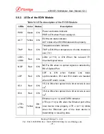
User can check the LEDs one the EOW to see the detail status
of the Multi-service Multiplexer Module. To do this, user should
first push the ‘ADDR’ button on the EOW Module to get the
right Address of the expected Multi-service Multiplexer Module.
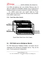
Please refer to the below figure to get the actual address of
every Multi-service Multiplexer module.


