background image

Connecting to Peripherals 

5


83 


notebook/networks through a local area network (LAN) and supports data 
transfer rates at 10Mbps and can be up to 100Mbps. The 10Base-T standard 
also called Twisted Pair Ethernet is connected with RJ-45 connectors. The 
100Base-TX is based on the older Ethernet standard. Because it is 10 times 
faster than Ethernet, it is often referred to as Fast Ethernet. 

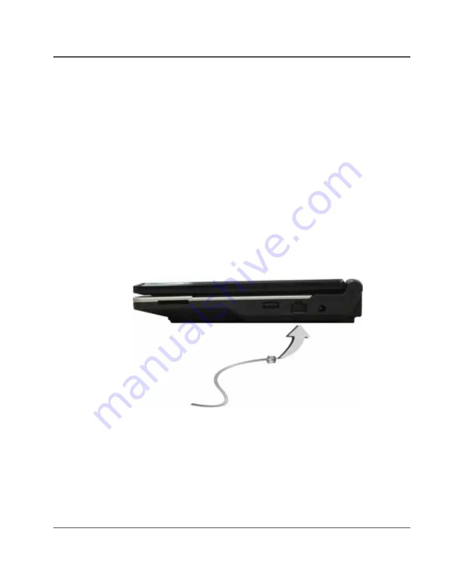
The built-in LAN module provides a standard RJ-45 connector.  

To connect the twisted-pair cable to your LAN port: 

1.


Locate the twisted-pair cable in the accessories box in Mini-note shipping 
carton. Each end of the cable has a RJ-45 connector. 

2.


Connect one end of the cable into the network wall outlet or HUB. 

3.


Connect the other end of the cable into the Mini-note RJ-45 LAN port. 


5.5  Using the Wireless LAN 

Wireless LAN lets user connect to the LAN environment without using any 
wire to traditional RJ-45 jack. User can enjoy the wireless connection within 
the range of Access Point (AP) of LAN.  

Summary of Contents for CW001

Page 1: ...CW001 Mini note User Guide ...

Page 2: ... identification purposes only and may be the trademarks of their respective companies Microsoft Windows XP Windows Vista and Windows Sound System are trademarks of Microsoft Corporation Intel Intel Atom Intel HD Audio Azalia are registered trademark of Intel Corporation Sound Blaster Sound Blaster Pro are trademarks of Creative Technology All other brands or product names mentioned in this manual ...

Page 3: ... receiver z Connect the equipment into an outlet on a circuit different from that to which the receiver is connected z Consult the dealer or an experienced radio TV technician for help FCC Declaration of conformity Model No CW001 Responsible party First International Computer Inc Address No 300 Yang Guang St Nei Hu Taipei Taiwan Telephone No 886 8751 8751 This device complies with Part 15 of the F...

Page 4: ...o maintain compliance with FCC RF exposure compliance requirements avoid direct contact to the transmitting antenna during transmitting Warning Use the specified shielded power cord and shielded signal cables with this computer so as not to interfere with radio and television reception If you use other cables it may cause interference with radio and television reception You may find helpful the fo...

Page 5: ...ipment other than manufacturer specified It is the responsibility of the user to correct any interference caused by such unauthorized modification substitution or attachment Manufacturer and its authorized resellers or distributors will assume no liability for any damage or violation of government regulations arising from failing to comply with these guidelines Canadian Department of Communication...

Page 6: ...lass 1 Laser Product Caution Changes or modifications not expressly approved by the manufacturer may void the user s authority which is granted by the Federal Communications Commission to operate this computer Use Conditions This part complies with Part 15 of the FCC Rules Operation is subject to the following conditions 1 this device may not cause harmful interference and 2 this device must accep...

Page 7: ...est was performed according to the following European standards EN 300 328 V 1 7 1 EN 301 489 1 V 1 6 1 EN 301 489 17 V 1 2 1 EN 50385 EN 60950 1 Regulatory statement R TTE European standards dictate maximum radiated transmit power of 100mW EIRP and frequency range 2 400 2 4835GHz In France the equipment must be restricted to the 2 4465 2 4835GHz frequency range and must be restricted to indoor us...

Page 8: ...ment from humidity 4 Do not use this product near water for example near a bathtub wash bowl kitchen sink or laundry tub in a wet basement or near a swimming pool 5 Avoid using a telephone other than a cordless type during an electrical storm There may be a remote risk of electric shock from lightning 6 Do not use the telephone to report a gas leak in a vicinity of the leak 7 Lay this equipment on...

Page 9: ...eed for service If the equipment has obvious sign of breakage 12 The unit can be operated at maximum ambient temperature of 35ºC 13 Li Ion battery is vulnerable do not charge it with other power adapter or it may cause fire or explosion 14 This product should be operated from the type of power indicated on the marking label If you are not sure of the type of power available consult your dealer or ...

Page 10: ...ical safety concerns only use telephone cables rated 26AWG or higher 4 Unplug this product from the wall outlet before cleaning Do not use liquid cleaners or aerosol cleaners Use a dry cloth for cleaning Ensure that no liquid enters the system Laser Compliance Statement The CD ROM DVD ROM CD RW DVD RW drive in this computer is a laser product The CD ROM DVD ROM CD RW DVD RW drive s classification ...

Page 11: ...ACEMENT INCORRECT DE LA BATTERIE REMPLACER UNIQUEMENT AVEC UNE BATTERIE DU MÊME TYPE OU D UN TYPE RECOMMANDÉ PAR LE CONSTRUCTEUR METTER AU RÉBUT LES BATTERIES USAGÉES CONFORMÉMENT AUX INSTRUCTIONS DU FABRICANT 3 German VORSICHT Explisionsgefahr bei unsachgemäßen Austausch der Batterie Ersatz nur durch denselben oder einem vom Hersteller empfohlenem ähnlichen Typ Entsorgung gebrauchter Batterien na...

Page 12: ...et paristo valmistajan ohjeiden mukaisesti Power Cord Set Requirements An approved power cord has to be used Make sure the socket and any extension cord s you use can support the total current load of all the connected devices Before cleaning the computer make sure it is disconnected from any external power supplies i e AC adapter The power cord set appliance coupler flexible cord and wall plug yo...

Page 13: ...e antenna or cable system is to be connected to your mini EPC make sure that the antenna or cable system is electrically grounded to provide some provide some protection against voltage surges and static charges Article 810 of the National Electrical Code ANSI NFPSA 70 provide information with regard to proper grounding of the mask and supporting structure grounding of the lead in wire to an anten...

Page 14: ... cable shield to the grounding system of the building as close to the point of cable entry as practical TV Antenna The TV antenna supplied with any TV Tuner module is intended for Indoor use only Please do not use your TV Tuner module outdoors Battery Pack Do not incinerate or disassemble may explode or release toxic materials Do not short circuit may cause burns ...

Page 15: ...Notebouide 15 About Your Mini note Congratulation for having purchased your new Mini note This Mini note incorporates the newest features to serve your daily needs easily for anywhere you go ...

Page 16: ...epts of your new Mini note This manual is divided into eight chapters Chapter 1 Introduction Chapter 2 Getting Started Chapter 3 Using Your Mini note Chapter 4 Multimedia Setup Chapter 5 Connecting External devices Chapter 6 System BIOS Setup Chapter 7 Upgrade Options Chapter 8 Care and Maintenance Appendix A System Specifications ...

Page 17: ... OF THE MINI NOTE 31 1 7 THE RIGHT SIDE OF THE MINI NOTE 32 1 8 THE UNDERSIDE OF THE MINI NOTE 34 1 9 MINI NOTE ACCESSORIES 35 2 GETTING STARTED 37 2 1 USING THE BATTERY PACK 38 Extending Battery Life 40 2 2 CONNECTING THE AC POWER SOURCE 41 2 3 STARTING YOUR MINI NOTE 42 2 4 ADJUSTING THE DISPLAY CONTROLS 43 2 5 DEVICE DRIVERS INSTALLATION 43 Installing Windows XP from Optical Disk Drive 44 Insta...

Page 18: ...DERSTANDING THE KEYBOARD FUNCTIONS 52 Basic Keyboard Functions 54 Cursor Control Keys 56 Screen Control Keys 56 Windows Hot Keys 57 Special Function Keys 57 3 3 USING THE TOUCHPAD POINTING DEVICE 59 3 4 CONFIGURING YOUR SCREEN DISPLAY 61 Possible Display Configurations 61 ChangingtheDisplayPropertiesunderWindows 62 3 5 KNOWING THE POWER SAVING FEATURES 62 3 6 WORKING WITH THE BUILT IN HDD 64 3 7 E...

Page 19: ... 81 5 3 USING THE EXTERNAL AUDIO SYSTEM 82 5 4 USING THE LAN PORT 82 5 5 USING THE WIRELESS LAN 83 6 CUSTOMIZING YOUR MINI NOTE 85 6 1 RUNNING THE BIOS SETUP PROGRAM 86 6 2 USING THE MAIN MENU SETUP 88 6 3 USING THE ADVANCED CMOS SETUP 90 6 4 SECURITY MENU SETUP 92 6 5 USING THE BOOT SETUP 93 6 6 HOW TO EXIT THE SETUP PROGRAM 94 6 7 HOW TO UPGRADE THE BIOS 95 7 USING OPTIONS 97 SYSTEM UPGRADE 97 7...

Page 20: ...RY CARE GUIDELINES 108 8 6 WHEN YOU TRAVEL 109 APPENDIX A SYSTEM SPECIFICATION 111 SYSTEM SPECIFICATION 112 Processor Unit 112 System Memory 112 LCD Display 112 VGA System 112 Storage 113 Audio System 113 ExpressCard 113 Webcam 113 Touchpad 113 Keyboard 114 Flash BIOS 114 I O Ports 114 Wireless devices 114 AC DC Power Supply Adapter 114 Battery 114 Weight and Dimension 115 ...

Page 21: ... sleek ultra portable computer This device matches all the demands for high performance computing and multimedia technology Your Mini note runs a wide variety to customize your special requirements personal productivity entertainment professional applications and especially ideal for use on the road ...

Page 22: ...eck with your dealer on the CPU type and speed Fully compatible with an entire library of PC software based on operating systems such as Windows XP Memory This Mini note provides one memory slot for installing DDRII SDRAM 200 pin SODIMM module up to 2GB using 512MB or 1024MB DDRII SDRAM module Wide Screen LCD Display Provides 10 1 1024 x 600 16 10 wide screen LCD display Wireless LAN IEEE 802 11b ...

Page 23: ...hard disk drives Support ultra DMA ATA 300 PIO Mode up to PIO Mode 4 bus mastering for LBA Scheme Audio System Compliant with Intel HD Audio Azalia Sound Blaster compatible Support 32 bit multi channel audio system output Flash BIOS Flash BIOS allows you to easily upgrade the System BIOS using the Phoenix Flash utility program Power and System Management Integrated SMM System Management Mode on sy...

Page 24: ...curely packaged in a sturdy cardboard shipping carton Upon receiving your Mini note open the carton and carefully remove the contents In addition to this User Guide the shipping carton should also contain the following items The Mini note An AC Adapter and AC Power Cord Li Ion Battery Pack CD Driver Utility and User Guide Quick Setup Manual Carefully inspect each component to make sure that nothin...

Page 25: ...Built in Stereo Speakers 4 Power On Resume Button 5 LED Indicators 6 Integrated Microphone 8 Easy Buttons 9 Keyboard 10 Touchpad Pointing Device Webcam The Webcam is 1 3M pixels It can be used as a communication device that transmits instant image through network for conference Color Widescreen LCD Display The Mini note comes with a color LCD that you can adjust for a comfortable viewing position ...

Page 26: ...dio output for your multimedia presentations or listening pleasure Power On Resume Button Switches the Mini note power on and off or resumes whenever it is in Suspend and Hibernate mode LED Indicators Keeps you informed of your Mini note current power status and operating status Description of the status icons appears in the latter part of this section Integrated Microphone Integrated mono microph...

Page 27: ...tons The two select buttons located at each side of the Touchpad support tapping selection and dragging functions These buttons work like a standard notebook mouse Simply move your fingertip over the Touchpad to control the position of the cursor Use the selection buttons at each side of the Touchpad to select menu items MINI NOTE STATUS ICONS The Status LED Panel keeps you informed of the Mini no...

Page 28: ...installed WLAN Bluetooth Access When LED turns on indicates that the wireless LAN Bluetooth module is activated When LED lights off it indicates that the function is disabled Drive Access When LED turns on indicates that the system is accessing the Hard Disk Drive Caps Lock When LED turns on indicates that the Caps Lock key on the keyboard is activated When activated all alphabet keys typed in wil...

Page 29: ...il Button This is the most convenient way to access the outlook utility just by pressing this button You can simplify several procedures in entering into Outlook environment Internet Button This technology is designed specifically for providing a very convenient way in connecting Internet only by pressing Internet button as shown in the graphics Just Press this button to open the Internet Explorer...

Page 30: ...icrophone for monophonic sound recording directly into your Mini note computer Headphone Jack Lets you plug in a stereo headphone powered speakers or earphone set with 1 8 inch phono plug for personal listening 1 5 The Rear Side of the Notebook The system ports at the back of your notebook computer can connect the devices as described followings ...

Page 31: ...ysically secure your Mini note VGA Port Lets you attach an external monitor or projector for wider display You can run the LCD display and the external monitor simultaneously or switch it to monitor only using the display hot key 1 6 The Left Side of the Mini note The left side of your Mini note provides the features shown in the following figure ...

Page 32: ...nd so on to your Mini note Air Outlet Vent Emits the heat out of your Mini note and keeps it within operating temperature ExpressCard Slot A newly developed PC Card interface its connector has 26 pins and has a potential transfer rate of up to 500 MB sec or 250 MB sec in each direction 1 7 The Right Side of the Mini note The right side of the Mini note offers the features shown in the following fi...

Page 33: ...torage media Please pay attention to correct direction when you insert the flash memory card For more detail of flash card you can refer to Chapter 3 7 USB 2 0 Port The Universal Serial Bus USB port allows you to connect USB 2 0 compliant devices for example printers scanners and so on to your Mini note LAN Port An internal 10Base T 100Base TX and 1G option Ethernet LAN module connects your comput...

Page 34: ...ment 2 Memory Compartment 3 Battery Lock Latch 4 Battery Bay 5 Wireless LAN Compartment 6 SIM Card Compartment 7 Hard Disk Compartment 8 Battery Release Latch Bottom of the System Memory Compartment There is one SO DIMM memory slot for installing memory module Battery Lock Latch Push the latch to the left side to lock and secure the battery This action is available to release the battery when the ...

Page 35: ...tment Open this cover of this compartment to replace with other Hard Disk Drive Please refer to Chapter 7 for how to replace it Battery Release Latch To release the battery first locate the Battery Lock Latch at the left side with unlock status then push the Battery Release Latch to the right end to remove the battery pack 1 9 Mini note Accessories AC Adapter The AC Adapter supplies external power...

Page 36: ...k The battery pack uses rechargeable Lithium Ion Li Ion battery cells that provide long computing hours when fully charged and power management enabled You should always leave the battery inside your Mini note even when using the AC adapter as it also acts as a back up power supply in case power from the AC adapter is cut off It is also very important to have the battery pack always charged to pre...

Page 37: ...d 2 37 2 Getting Started Your Mini note is designed and pre configured for easy setup and use This chapter describes the installation steps you should follow to get the Mini note up and running as quickly as possible ...

Page 38: ...ssible relying on the battery pack only when AC power is unavailable When you use your Mini note the first time please operate it without an external power source You can connect the AC power adapter to immediately recharge the battery when the battery pack is used up and the mini note is turn off If you do not discharge the battery completely it fails to accept a full recharge Li Ion battery is v...

Page 39: ...ed nose directed toward the compartment insert and push the battery pack Removing the Battery Pack To remove the battery pack slide the lock latch to the end of right side to unlock the battery lock latch 1 then slide the battery release latch to the end of left side to release the battery latch 2 and take out the battery pack with your finger 3 simultaneously ...

Page 40: ...hard disk drive You will be unable to restart the Mini note until you have connected to the AC adapter or installed a charged battery To replace the battery pack refer to the previous sections on Installing the Battery Pack and Removing the Battery Pack For Window XP the suspend mode Hibernate or Standby can be chosen at Power Options of Windows s Control Panel Be sure to save your data before rep...

Page 41: ...nnect the power adapter 1 Plug the AC power cord into the power socket of the AC power adapter 2 Plug the other end of the AC power cord to a live AC wall outlet 3 Plug the connector of the AC adapter to the DC IN port found at the right side of the Mini note Whenever possible it is advisable to always have the AC adapter connected to the Mini note and the battery pack installed This ensures conti...

Page 42: ... supplies i e AC adapter 2 3 Starting Your Mini note The Power Resume button is found on the left top of the base unit Press the Power Resume button to start your Mini note and check that if the Power LED turns on After a few seconds the Mini note s display will turn on and your Mini note will begin to execute the Power On Self Test or POST to check if all system components are running properly An...

Page 43: ... adjustment is controlled by Fn F8 and Fn F9 keys respectively You need to press these hot key controls after powering on your Mini note to suit your viewing pleasure The Brightness hot key control adjusts the brightness on the LCD The brightness hot key control will not set the LCD completely dark or bright it provides sufficient lighting to the LCD to match the external lighting of the surroundi...

Page 44: ...ipset and VGA driver first The Bluetooth and Camera devices must be activated before installing Bluetooth or Camera driver INSTALLING THE CHIPSET DRIVER Your Mini note uses the advanced chipset Installing the driver to enhance the stability and performance Installing Chipset device driver for Windows XP 1 Click the Start button then point to Run The Run dialog box appears 2 Click the Browse button...

Page 45: ...nXP VGA Setup exe 3 Click OK to execute the setup program The Setup box appears 4 Click Next continuously to install this driver when screen displays this command 5 Click Yes continuously to install driver 6 Click Next twice to continue the installation 7 Tick the option Yes I want to restart my computer now and press Finish to restart your system INSTALLING THE AUDIO DEVICE DRIVER Your Mini note ...

Page 46: ... Run dialog box appears 2 Click the Browse button and specify the directory as E Drivers WinXP Touch Pad setup exe 3 Click OK to execute the setup program The Setup box appears 4 Click Next to continue the installation 5 Click Finish to complete the installation 6 Click Yes to restart your system INSTALLING THE AZUREWAVE WIRELESS LAN DEVICE DRIVER IEEE 802 11 B G Please follow the procedures below...

Page 47: ...ppears 2 Click the Browse button and specify the directory as E Drivers WinXP Bluetooth Setup exe 3 Click OK to execute the setup program The Setup box appears 4 Click Next to continue the following steps 5 Choose I accept the terms in the license agreement and click Next 6 Click Install to implement setup program to install this driver 7 Click Finish and then press Yes to restart your system INST...

Page 48: ...point to Run The Run dialog box appears 2 Click the Browse button and specify the directory as E Drivers WinXP Card Reader setup exe 3 Click OK to execute the setup program The Setup box appears 4 Click OK to complete the installation INSTALLING THE CAMERA DEVICE UTILITY Please follow the procedures below for installing the Camera utility Installing Camera utility for Windows XP 1 Click the Start ...

Page 49: ...e computer now and press Finish to restart your system 2 6 Turning off Your Mini note If you are not going to use the Mini note for a while it is best to turn off the power of the Mini note Before turning off the power you need to first close all application programs and shut down the operating system After turning off the Mini note make it a habit to leave the LCD panel open for a while whenever ...

Page 50: ...Mini note User Guide 50 This page is intended to be blank ...

Page 51: ...Using Your Mini note3 51 3 Using Your Mini note This chapter describes how to operate the standard built in features of the Mini note ...

Page 52: ...crosoft Windows The Mini note comes with an operating system pre installed and needs only to be setup and configured during initial use 3 2 Understanding the Keyboard Functions Your Mini note is equipped with an 83 keys keyboard that provides all the functionality of a full sized 101 or 102 key keyboard Aside from the standard typewriter layout keyboard of your Mini note there are a number of extr...

Page 53: ... keyboard These keys work together with the Fn key to activate special functions Some keys printed in blue on keypad are preprogrammed with dual functions Control keys Ctrl Alt Fn and Shift are controls used in conjunction with other keys to change their functions To use control keys press and hold the control key while pressing another key For example Press Ctrl C means to hold down the Ctrl key ...

Page 54: ...The cursor indicates where the next text typed is inserted Typewriter keys Typewriter keys also called alphanumeric keys are used to enter text and characters Keys with blue print on them behave differently when combined with control keys BASIC KEYBOARD FUNCTIONS Keypad Function Description Enter key Execute a command Within many text editing application programs the Enter key inserts a hard carri...

Page 55: ...typing Use this key in combination with those two character keys found on the second row of the keyboard to produce the upper marked keys Also used in most application program in combination with other keys to execute a certain command Tab key Press this key to move the cursor to the next tab stop on the right This key works much the same as in ordinary typewriter Ctrl key Known as the Control key...

Page 56: ...n Up arrow key Moves the cursor up one line at a time Down arrow key Moves the cursor down one line at a time Left arrow key Moves the cursor to the left one space at a time Right arrow key Moves the cursor to the right one space at a time SCREEN CONTROL KEYS Keypad Function Description Fn Home key Moves the cursor to the beginning of a screen or line Fn PgUp key Moves the cursor up one screen at ...

Page 57: ...YS Keypad Function Description Start key Pulls up the Windows Start menu Right Click key Performs a mouse right click function for Windows system SPECIAL FUNCTION KEYS The Mini note has special system function keys that activate key serving dual functions When pressed in conjunction with the Fn key these keys set specific system parameters and are sometimes referred to as hot keys ...

Page 58: ...LAN function Switches display between LCD CRT or LCD and CRT simultaneously To enable or disable the 3 5G HSPDA 802 11b g n function To mute or open the built in system speaker To activate or deactivate the touchpad function Decrease the brightness of LCD display incrementally Increases the brightness of LCD display incrementally ...

Page 59: ...l and double click on the Mouse icon The options let you control the size and color of the cursor cursor speed the accepted double click speed and selection button orientation The Touchpad works a mouse pointing device replacement that is used under Windows based operating system You can use the standard Microsoft driver that is compatible with the Touchpad device and is normally used under Window...

Page 60: ...ve the mouse cursor place the finger lightly on the sensor pad and move in the desired direction If you reach the end of the pad lift your finger and place it back down on the other side of the pad 2 To select an item click on the item by pressing the left button control or by simply tapping on the surface once A light quick tap always works best To execute an item click the left button twice or d...

Page 61: ...and high frequency CRT or LCD Please Refer to Section 5 Installing the Mini note Device Drivers of Chapter 2 in this manual for the procedures on how to install the VGA device driver under Windows After installing the VGA driver you would then configure the display resolution or screen size to match your LCD display panel This Mini note model provides Wide screen 10 1 1024 x 600 WSVGA resolution p...

Page 62: ...een Click on the Settings tab to set your desired configuration Make sure to follow the configuration table above If you cannot configure the display properties change the display driver first as mentioned on Section 5 Installing the Mini note Device Drivers of Chapter 2 in this manual Consult your dealer for the latest Windows VGA driver 3 5 Knowing the Power Saving Features Aside from its superi...

Page 63: ... again you can press the power button to return your work to the screen where you left off Hibernation Mode In Hibernation mode all system devices are powered down and the contents of RAM are stored on your hard drive Hibernate mode uses less power than Standby mode but takes a bit longer time to resume When your Mini note goes into hibernation Windows saves your entire desktop state before poweri...

Page 64: ...puter is turn on and start using it immediately Inserting ExpressCard To insert a ExpressCard into the ExpressCard slot 1 Locate the ExpressCard slot cover on the right side of the computer 2 Insert the side of ExpressCard into the ExpressCard slot The face label of the card should also be facing up 3 When the full length of the card is almost inside the slot push firmly but slowly to ensure full ...

Page 65: ... the task bar 2 Select the socket from the list that you want to remove and click Stop button The system then disables the function of ExpressCard card 3 Then you can remove the inserted ExpressCard To release the ExpressCard just push the ExpressCard again to the end Then the ExpressCard will automatically bounce off the ExpressCard slot 4 When the ExpressCard has moved out a space out of the slo...

Page 66: ... when it is not in use 3 8 Using Flash Memory Cards FLASH MEMORY CARD Flash Memory is a memory storage media It is used by most digital camera Flash memory card is built with different form factor and brand name The 4 in 1 card slot in this Mini note supports following cards as SD MS Memory Stick MMC and MS_Pro For a single moment only one card can be inserted into the 4 in 1 card slot ...

Page 67: ...er of the slots in inserting Only one correct side can be accepted for the 4 in 1 card slot If you cannot insert the card into the 4 in 1 slot or you had inserted the card but it is not recognized by the computer please remove the card and insert it again To prevent the damage made both on card and the slot never forced an entry into the slot with incorrect side Removing Flash Memory Card To remov...

Page 68: ...Mini note User Guide 68 ...

Page 69: ...Fun with Multimedia 4 69 4 Fun with Multimedia This chapter lets you make full use of all the multimedia features of your Mini note in having fun and excitement during work or leisure ...

Page 70: ... compatible 4 2 Audio Sound System Features Your Mini note has a built in 16 bit stereo sound controller that allows you to record store and playback voice music and other sound effects with built in mixer controls An integrated full duplex microphone and twin mini speakers are also built in into your Mini note to allow you to record and playback sound anytime and anywhere At the front side of you...

Page 71: ...installed it is most likely that your dealer have configured the sound driver for you If not you must refer to Chapter 2 on how to setup the sound drivers for Windows 4 4 Windows Multimedia Programs Windows provides several multimedia programs that you can run with the built in features of your Mini note Pointing the Start button Programs Accessories then Entertainment you will find the Multimedia...

Page 72: ...ound Recorder for recording sounds and playback Volume Control for adjusting the volume of mixer For more information on how to operate these multimedia components run the program and click on the Help menu 4 5 Recording Sounds Your Mini note allows you to record voice and other sounds in several ways and stores them as files on your hard disk These voice or sound files can then ...

Page 73: ...simple to understand which comprise of the Fast Rewind Fast Forward Play Stop and Record buttons Click the Help menu on how to operate the Sound Recorder Figure 4 2 Sound Recorder The Sound Recorder also allows you to record sound from different input audio source like the following From the external microphone From the USB Slim Combo Drive optional Since you could record sound from different inpu...

Page 74: ... component that list in the Shows the following Volume Controls box Figure 4 3 Audio Properties 4 Click OK and the Recording Control dialog box will appear Here you will select the input device for the recording source If you want to record from the USB Slim Combo Drive optional with audio music you must click on stereo mix ...

Page 75: ... with 1 8 inch mini jack connector Follow the same procedure for recording voice 4 6 Playing Audio and Sound Your Mini note has built in twin speakers to playback audio and sound You can also adjust the volume manually by adjusting the volume control hotkeys found on the keyboard For more quality sound output you can choose to connect an external amplified speaker or earphone from headphone jack A...

Page 76: ...ile menu and select the file you want to play 4 When the file is recognized and open click on the Play button to start playback 4 7 Playing Video and MPEG Files Your Mini note is capable of running video motion files as well as MPEG Motion Picture Expert Group files on CD DVD or CD RW By using software MPEG program you can watch real full motion picture on your Mini note You can also run the Windo...

Page 77: ...Fun with Multimedia 4 77 Figure 4 6 Windows Media Player ...

Page 78: ...Mini note User Guide 78 This page is intended to be blank ...

Page 79: ...chapter describes how you attach additional peripheral devices to your Mini note The Mini note allows you to add a printer or mouse connect an external monitor and keyboard or other compatible peripheral device Use of additional devices is described in this chapter ...

Page 80: ... to have worked on USB 2 0 standardization USB 2 0 offers data transfer rate up to 480Mbps megabits per second compared to USB 1 1 devices which transfer at speeds of 12Mbps So you could know that USB 2 0 can transfer data between the Mini note and its peripherals 40 times faster than USB 1 1 However USB 2 0 is fully backward compatible you will be able to use a USB 1 1 device in a USB 2 0 complia...

Page 81: ...off the computer and the external monitor however it is harmful to both devices and it shortens the life of these devices 2 Connect the connector cable of the monitor to the VGA port at the back of your computer 3 Connect the monitor power cable and plug it into a properly grounded wall outlet 4 Turn on the power of the monitor 5 Turn on your computer Both the LCD panel and the monitor screen will...

Page 82: ...the audio port Microphone Headphone that you want to use to the target device 2 Plug the jack into the port on the front side of the system If you use external speaker and experience the sound distortion or feedback please lower the volume Some factors is caused by too close locating the microphone and speaker from each other moving away the external audio option from the unit may also help 5 4 Us...

Page 83: ... built in LAN module provides a standard RJ 45 connector To connect the twisted pair cable to your LAN port 1 Locate the twisted pair cable in the accessories box in Mini note shipping carton Each end of the cable has a RJ 45 connector 2 Connect one end of the cable into the network wall outlet or HUB 3 Connect the other end of the cable into the Mini note RJ 45 LAN port 5 5 Using the Wireless LAN...

Page 84: ...ry In most case you probably can use it at office please consult with the network department of your company for more details This Mini note integrates built in 802 11b g wireless LAN module IEEE 802 11b standard supports 11 Mbps wireless connection speed However IEEE 802 11g supports 54Mbps wireless connection speed and is backward compatible with the slower 802 11b Wireless LAN module is similar...

Page 85: ...your computing needs User adjustable options include system time and date disk drive configuration and password setup BIOS information stored in the CMOS RAM will remain permanent unless changed Default factory settings are used top optimize performance of your Mini note and do not need further alteration to operate your Mini note Use caution when changing any BIOS settings ...

Page 86: ...enever you turn on the Mini note the system will read the settings stored in the CMOS RAM and compare them to the equipment check conducted during the Power On Self Test POST If an error occurs an error message will be displayed on the screen and you will then be prompted to run the Setup Program Press the F2 key to run the BIOS Setup program The BIOS Setup program is organized into five menus whi...

Page 87: ...his area lists the parameters and their current settings Key Status Bar The bottom part of the screen These lines display the keys available to move the cursor select a particular function and so forth To exit the BIOS Setup program simply press the Esc key and select from the Exit menu whether you want to Save Changes Discard Changes and Exit Discard Changes ...

Page 88: ...Type Intel R Atom TM CPU N270 CPU Speed 1600 MHz System Memory 640 KB Extended Memory 1038336 KB F1 Help Select Item Change Values F9 Setup Defaults Esc Exit Select Menu Enter Select Sub Menu F10 Save and Exit System Time Allows you to change the system time using the hour minute second format of the Enter the current time for reach field and use the Tab Shift Tab or Enter key to move from one fie...

Page 89: ...e storage media CPU Type This field reports the CPU type information detected by the BIOS during Power On Self Test POST CPU Speed This field reports the CPU speed information detected by the BIOS during Power On Self Test POST System Memory This field reports the amount of base or conventional memory found by the BIOS during Power On Self Test POST Extended Memory This field reports the amount of...

Page 90: ...Disabled Bus Total Graphics Memory MaxDVMT DVMT Graphics Memory 216MB Energy Star Support Enabled F1 Help Select Item Change Values F9 Setup Defaults Esc Exit Select Menu Enter Select Sub Menu F10 Save and Exit Legacy USB Support Enable or Disable the Legacy Universal Serial Bus support USB Device 29 Function 7 Enable or Disable the USB 2 0 controller support Boot time Diagnostic Screen Lets you c...

Page 91: ... Lets you select total graphics memory size for internal graphics device The Options are 64MB 128MB and MaxDVMT DVMT Graphics Memory Display DVMT graphics memory size Energy Star Support Lets you activate or inactivate the function of Energy Star Support ...

Page 92: ...enu F10 Save and Exit Supervisor Password Is Set Clear selections show that the Mini note is under controlled by Supervisor Password or not User Password Is Set Clear selections show that the Mini note is under controlled by User Password or not Set Supervisor Password Supervisor password gives you the authority in accessing the setup utility You also need to enter this password in system booting ...

Page 93: ...em allows you to set the search drive sequence where the system will try to boot up first Phoenix BIOS Setup Utility Main Advanced Security Boot Exit LAN BOOT Disabled Item Specific Help Enable LAN boot Boot priority order 1 USB FDC 2 USB CDROM 3 USB KEY 4 USB HDD 5 IDE HDD FUJITSU MHZ2120BH G2 S1 6 PCI BEV F1 Help Select Item Change Values F9 Setup Defaults Esc Exit Select Menu Enter Select Sub M...

Page 94: ... to Exit the Setup Program There are two choices to escape from the Setup program Phoenix BIOS Setup Utility Main Advanced Security Boot Exit Item Specific Help Exit Saving Changes Exit System Setup Exit Discarding Changes and save your Load Setup Defaults changes to CMOS Discard Changes Save Changes F1 Help Select Item Change Values F9 Setup Defaults Esc Exit Select Menu Enter Select Sub Menu F10...

Page 95: ...sily upgrade the BIOS program When you update the BIOS any customized settings you made are lost To upgrade the BIOS 1 Put in the BIOS Update data into the USB device 2 Power on the system with the diskette in the diskette drive 3 On the DOS prompt type the following command A Phlash XXXXXX ROM BIOS filename or A XXXXXX BAT Batch file for BIOS file Press Enter to run this BIOS utility After the sy...

Page 96: ...Mini note User Guide 96 4 Press any key to restart this system Contact your dealer for the latest BIOS update file ...

Page 97: ...Using Options 7 97 7 Using Options This chapter describes the advanced features and expandable architecture in your Mini note ...

Page 98: ...DDR SDRAM The memory compartment is located inside your computer Please contact dealer for changing or adding DDR2 SDRAM module It is not available for users to change it by themselves INSTALLING MEMORY MODULE Your computer comes with standard 512MB or 1024MB of synchronous DDR2 SO DIMM The 512MB and 1024MB memory modules are available To install the memory module 1 Make sure the system is powered...

Page 99: ...y damage the system 4 Insert the connector of the memory module into the socket Make sure the notch of the memory module fits the nose of the socket Hold the memory module at a 30 degree angle and push its connector into the memory socket of the notebook Press down on the edge of the memory module until the locking tabs on both sides is locked 5 Put the DIMM door back and secure the screw on the D...

Page 100: ...d or it is crashed you can upgrade it by replacing with new hard disk Please do the following steps to change it 1 Remove the screw and open the cover by lifting its upper side cover 2 Take out the hard disk from the compartment by finger carefully 3 Remove the screws and connector from the hard disk gently 4 Remove the crane screws located at each side of the hard disk 5 Rotate and tighten the cr...

Page 101: ...tically and prompt you how to format the new disk Please tighten the screws located at each side of the hard disk before operating the hard disk Any vibration may cause damage for the running hard disk Please contact dealer or certified technician for changing the hard disk drive The damage of changing HDD resulting from users may not be under warranty 7 3 Wireless Module Installation This Mini no...

Page 102: ......

Page 103: ... 8 103 8 Caring for Your Mini note Your Mini note the latest features in mobile computing and multimedia technology If properly cared for and maintained the performance and reliability of the Mini note can be greatly prolonged ...

Page 104: ...et or a cloth for cleaning The socket outlet shall be installed near the Mini note and shall be easily accessible Please keep the Mini note away from humidity Lay the Mini note on a reliable flat surface when operating A drop or fall may cause injury The openings on the enclosure are for air convection hence the Mini note can be protected from overheating DO NOT COVER THE OPENINGS Be careful of us...

Page 105: ...ect it from mains to avoid possible damage by transient over voltage Never pour any liquid into openings as this may cause fire or electrical shock Never open the body of Mini note For safety reason the Mini note should only be opened by qualified service personnel If one of the following situations arises have the Mini note checked by service personnel The power cord or plug is damaged Liquid has...

Page 106: ...gents to clean the Mini note Also never spray any liquids directly on the Mini note case keyboard or screen If the liquid crystal display LCD screen has become smeared or dusty clean the screen by first applying a mild glass cleaner to a soft clean lint free cloth and gently wipe the glass Never apply liquids directly on the screen surface Moreover do not use paper towels to clean the display scre...

Page 107: ...maintenance you could do Always back up your data files from your hard disk Install the virus detecting program to monitor virus that could tamper your files Use SCANDISK occasionally to correct any errors found in the directory and File Allocation Table This will also free up space from any unused sectors Never move or raise the Mini note while the hard disk is being accessed most especially don ...

Page 108: ...bed in this manual and only in ventilated areas Never use an external charger other than the one supplied with your Mini note Do not leave batteries in hot locations for more than a day or two Do not leave your battery in your Mini note for longer than 1 month without plugging in the power adapter Do not leave battery in storage for more than 2 months without recharging it to prevent over discharg...

Page 109: ...ave Don t forget to bring along the AC adapter and extra battery pack Try to bring backup software as well Check the voltage rating and the outlet type of your destination If the power cord of the adapter is different then you need to purchase a suitable one Consult your dealer Carry your Mini note in its carrying case or in a briefcase Never check in the Mini note as a luggage Remember to apply t...

Page 110: ...Mini note User Guide 110 This page is intended to be blank ...

Page 111: ...System Specification A 111 APPENDIX A System Specification This appendix provides technical specifications for the Mini note ...

Page 112: ...t 512MB and 1024MB memory modules using 200 pin SODIMM DDR2 533 667 SDRAM modules Maximum memory size 2GB LCD DISPLAY 10 1 WSXGA 16 10 Color TFT LCD 1024 x 600 Maximum 16M true colors on all LCD display VGA SYSTEM Integrated Intel 945 GSE graphic engine Simultaneous LCD and external monitor CRT display Maximum 16 million colors on LCD display at 1024 x 600 resolution CRT only for 10 1 LCD ...

Page 113: ...vice 4 in 1 SD MS MMC and MS_Pro card reader AUDIO SYSTEM Compliant with Intel HD Audio Azalia 2 channels H W Audio Sound Blaster 16 compatible Built in dual speakers Audio input jacks for microphone MIC Audio output jack for external speaker or headphone Line Out Sound volume adjust by K B Hot Keys EXPRESSCARD One 34mm PCI ExpressCard slot WEBCAM One Webcam with USB2 0 CMOS 1 3M pixel TOUCHPAD In...

Page 114: ...ash ROM BIOS for easy BIOS upgrade I O PORTS 1 x VGA port 2 x Universal Serial Bus USB 2 0 1 x 10Base T 100Base TX LAN port 1G Option WIRELESS DEVICES IEEE 802 11b g Half Mini PCI card Bluetooth USB Interface AC DC POWER SUPPLY ADAPTER Universal auto switching 100V 240V 40W adapter 20 Volt BATTERY Rechargeable 4 Cells Li ion battery pack with Smart Battery function Approximately 4 5 Hours for 4 Ce...

Page 115: ...System Specification A 115 WEIGHT AND DIMENSION 263 W x 185 D x 19 6 27 H mm Approximately 1 3 kg ...

Page 116: ...Mini note User Guide 116 ...

Reviews: