


4
www.fiduspower.com
ULP275
Series
ULP275
Series
WLP350
Series
VPS1000
Series
AC Power Derating Curve
0
85
95
105
115
100
80
60
40
20
70
120
125
135
255
265
Application notes
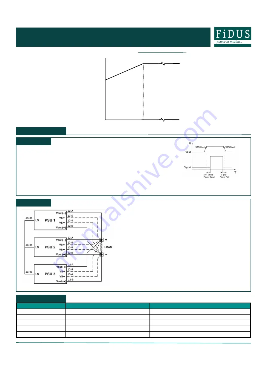
Load share
The volt sense lines must all be connected to one point and the output voltage of each the
power supplies must be adjusted to be within 1% for the current share to operate. Should they
not be adjusted the current share will not function. When using the load share function derate
the cumulative power total by 10%. Please follow the below step by step process to ensure
smooth operation:
•
Connect all output cables to Vout
•
Connect all Vs cables and twist pairs together
•
Terminate all the Vs lines to the same +/
-
points
•
Connect the load share (LS pin 10 on J3) of all the units
•
With other units tuned off, on each PSU use the output adjust to change
Vout within 1%
•
The current share should be checked with a DC hall sensor showing that
the power supplies share the current within 10%
Signals
Power Good
: TTL output activated at 90% of Vout. Delay between 100 and 500mS
At least 1mS before Vout falls below 90% TTL signal switches low
Remote Sense:
Compensation for 200mV voltage drop on cable runs
Remote on/off:
Unit comes pre
-
configured with pin 6 & 7 shorted to enable the unit
Current limit:
Do not remove. This feature is not field configurable.
VPS800
Series
MVPS800
Series
Safety standard
Notes & Conditions
UL/CSA
ANSI/AMMI ES 60601
-
1, CSA C22
-
2 NO
-
60601
-
1
UL Certificate No : 20190221
-
E173812
CB
IEC60601
-
1 3rd ed
CB Test Certificate No : NO105338
Nemko
EN60601
-
1 3rd ed
Nemko Certificate No : P19223365
CE
2015/863/EU RoHS Directive and 2014/35/EU Low voltage directive
Equipment protection class
Class I
Safety Approvals


