6
www.fiduspower.com
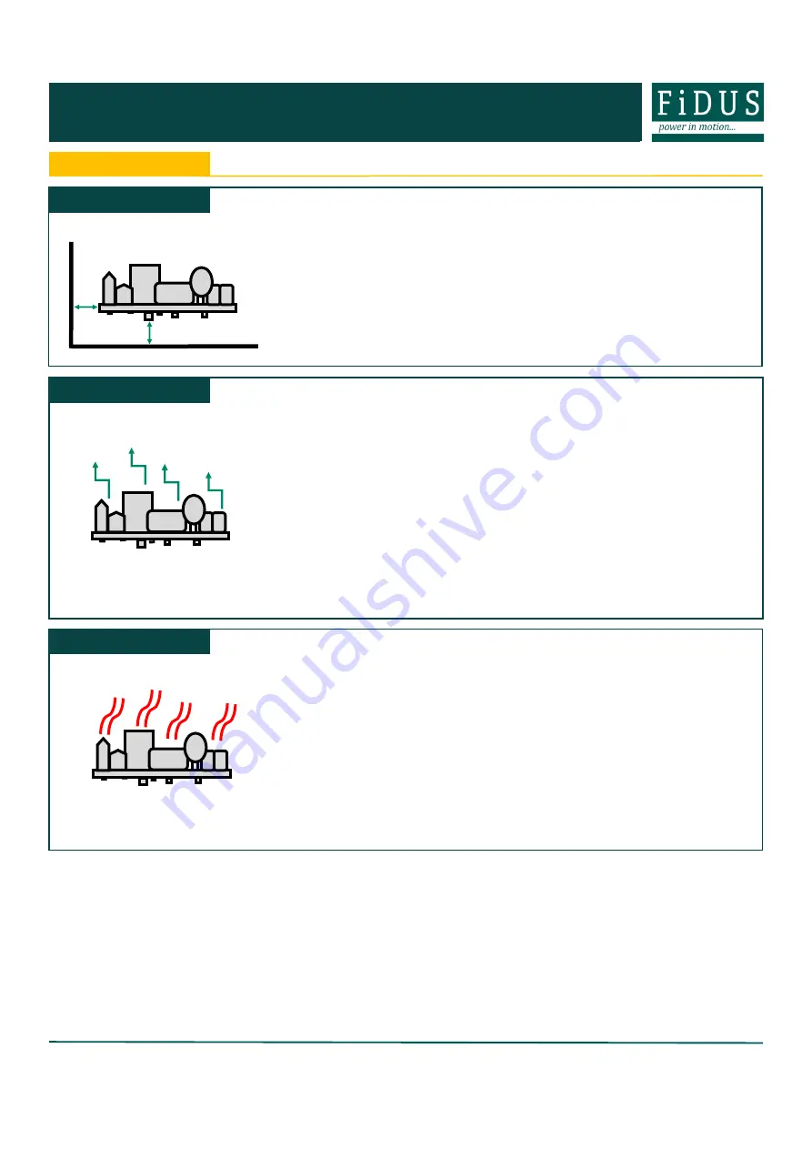
Thermal
Thermal management is an important consideration when thinking about equipment service life. Electrolytic
capacitors within the PSU wear with time and are typically the first end
-
of
-
life failure. Keeping the operation
temperature of key components within the PSU, such as the electrolytic capacitors, as low as possible is para-
mount. As a general rule, for every 10°C drop in the operating temperature of the electrolytic capacitators you
double their lifetime, and thus the lifetime of the power supply. When looking at thermal performance it is helpful
to test under a worst
-
case set of conditions, to ensure component temperatures are in an acceptable range for
the required service life. Then consider the impact of operational time, load and temperature profile to estimate
a more realistic lifetime for your PSU.
Also, many FiDUS power supplies offer a
Peak Power
rating to provide for customers with pulsing loads. When
using a peak power capability customers must consider:
1)
Peak duration rating: the maximum length of time the peak can be drawn for
2)
Duty cycle: the frequency with which the peak can be drawn. (e.g. 10% duty cycle, 1 second on:9 seconds
off)
3)
Average power value: datasheets will state the maximum average power acceptable with peak power PSUs.
If any of these elements are exceeded the supply may overheat, with performance and lifetime suffering as a
result.
Installation Advice
Conducted and radiated emissions compliance is a common application consideration. It is important to remem-
ber that even when using a properly filtered PSU, an application may still not achieve compliance if it is not de-
signed to minimise emissions. That being said, there are a number of things that can be done to optimise EMC
performance either as best practice, or if you are struggling for compliance:
1)
Connect all marked EMI ground points to earth. Often these are combined with the safety earth point (in class
I installations), but on some power supplies there may be additional earth tags or mounting points.
2)
Minimise the length of input/output wiring where possible and try to maintain max distance of the conductors
from the PSU, to prevent noise pick up. Avoid bundling input and output cables together. A common component
to avoid placing wiring near is the PFC inductor in power factor corrected power supplies.
3)
Apply additional filtering before the PSU input (ensure consideration of which frequencies there are issues
with before selecting a filter).
4)
When using an open frame PSU, mount the supply on a metal plate and connect EMI mounting points.
5)
In multi circuit systems, decouple the circuits locally.
6)
Ferrites added between the PSU and system input connector and/or the DC output cables can help in reduc-
ing radiated noise issues in systems. If seen, issues are commonly in the 30
-
150MHz area.
For more detailed assistance, if you still have any concerns with compliance, please get in contact with our Engi-
neering department who are on hand to assist with any queries.
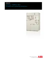
EMC
On installation customers must consider the required creepage and clearance distances between the PSU and
the end
-
equipment enclosure. These distances vary depending on the installation class and safety standard
requirements.
For
Class I
installations there should be 3
-
4mm between any part of the PSU and any earthed metal part of the
enclosure. 3mm is acceptable for IT applications, 4mm required for medical applications. In Class I installations
the PSU earth point must be connected to system safety ground.
For
Class II
installations distances may need to be increased if being installed into a surrounding metal enclo-
sure.
Ensure consideration of components on the underside of the PCB or low lying spills when measuring clearance
distances between the PSU and the end
-
equipment. Also top surface especially in tight enclosures such as 1U
boxes. An insulation material can be used between PSU and metal if smaller gap required.
FiDUS recommends installing the PSU on 6mm stand offs typically, but check the distances.
Safety
ULP275
Series
WLP350
Series
VPS1000
Series
VPS800
Series
MVPS800
Series
11/10/22