background image


Page 3

8.  Draw a horizontal line on Diagram A or B that passes through the point located in step 5. The 

position of the point along this line relative to the left and right borders of the region it falls into 
indicates the relative position that the balance weight of the VRV should be adjusted to. If the 
point falls near the leftward border of a region, then the VRV balance weight should be adjusted to 
it's minimum position. This corresponds to turning the balance weight screw as far counter-
clockwise as possible. 

EXAMPLE:


An oil fired appliance firing at 1.0 gph where the CAS unit needs to be placed 30 

equivalent feet from the intake hood. 

From Diagram A or B, the point at 1.0 gph on the "Oil Firing Rate" scale and 30 
equivalent feet falls in the "4 inch Duct, Hood, and Orifice Ring" region. The point 
is in between the left and right boundary of the region. The left boundary is the 
edge of the graph, the right boundary is the diagonal line that says "4 inch Duct, 
Hood & Orifice Ring." Therefore, place the Orifice Ring into the inlet on the CAS 
so that it sits on the ledge above the fan. It does not matter which way the Orifice 
Ring is turned as long as it is pushed down against the ledge completely. Use 4" 
diameter pipe to connect the vent hood and the CAS unit. Install a VRV and the 
included 4x6 Increaser on top of the CAS unit and adjust the balance weight to 
3/4 of the distance of it's full adjustment range from it's minimum setting. The 
minimum setting is with the balance weight turned all of the way counter-
clockwise. 

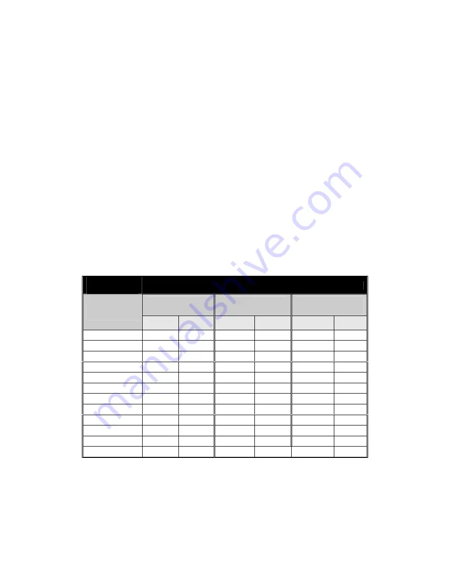
Total Input of 

Appliance 

Maximum Equivalent Feet of Installation 

4” Duct And Hood 

W/Restrictor 

4” Duct And 4” 

Intake Air Hood 

6” Duct And 6” 

Intake Air Hood 

CAS-3 

Oil (gph) 

HI 

LOW 

HI 

LOW 

HI 

LOW 

0.50 300 

300 

300 

300 

300 

300 

0.75 300 

300 

300 

300 

300 

300 

0.90 300 

220 

300 

220 

300 

300 

1.00 174 

108 

232 

118 

300 

300 

1.25 99 

48 

152 

63 

300 

300 

1.35 52 

14 

102 

32 

300 

300 

1.55 20 

NA 

68 

13 

300 

239 

1.75 NA 

NA 

45 

NA 

300 

150 

2.00 NA 

NA 

16 

NA 

300 

53 

2.50 NA 

NA 

NA 

NA 

193 

2.75 NA 

NA 

NA 

NA 

109 

NA 

3.25 NA 

NA 

NA 

NA 

56 

NA 

Table 1 

Summary of Contents for 46261200

Page 1: ...t work and the input rating of the appliance This device MUST be installed by a qualified agency in accordance with the manufacturers installation instructions The definition of a qualified agency is...

Page 2: ...ould be used when installing the CAS system Using these charts will help ensure that the proper amount of air is drawn into the structure as needed by the appliance The defined regions shown correspon...

Page 3: ...ry is the diagonal line that says 4 inch Duct Hood Orifice Ring Therefore place the Orifice Ring into the inlet on the CAS so that it sits on the ledge above the fan It does not matter which way the O...

Page 4: ...FIRING RATE gallons per hour 1 gallon oil hr 140 000 BTU hr 6 Duct Hood 4 Duct Hood 4 Duct Hood Orifice Diagram A LOW SPEED SIZING CHART 0 50 100 150 200 250 300 0 50 100 150 200 250 300 350 400 GAS I...

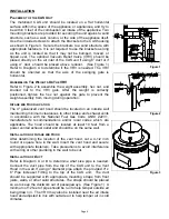
Page 5: ...moving during operation INTAKE AIR HOOD LOCATION The 4 galvanized vent hood should be located on an outside wall maintaining minimum clearances to other intake and exhaust vents in accordance with the...

Page 6: ...terminals Use the enclosed conduit connector s to route the appropriate wires through the CAS housing The incoming ground wire must be attached to the green colored ground screw near the wire termina...

Page 7: ...Page 7 Figure 6 Riello Oil Fired System Figure 7 Single Vent Oil Fired System...

Page 8: ...Page 8 Figure 8 Chimney Vent Two Oil Fired System with CAC 120...

Page 9: ...4 Clear any obstructions if present from the inlet of the vent hood and the outlet of the CAS unit 5 Periodically the fan blade chamber may need cleaning First disconnect the power supply to the CAS...

Page 10: ...t must be disassembled If this is necessary take note of the positions and locations of whatever items that may need to be removed to replace other items If in doubt please consult the Field Controls...

Page 11: ...Page 11 NOTES...

Page 12: ...Page 12 PN 46261200 Rev I 10 06...

Reviews: