background image

2630 Airport Road · Kinston, NC 28504 

Phone: 252-522-3031· Fax: 252-522-0214 

www.fieldcontrols.com


2630 Airport Road · Kinston, NC 28504 

Phone: 252-522-3031· Fax: 252-522-0214 

www.fieldcontrols.com


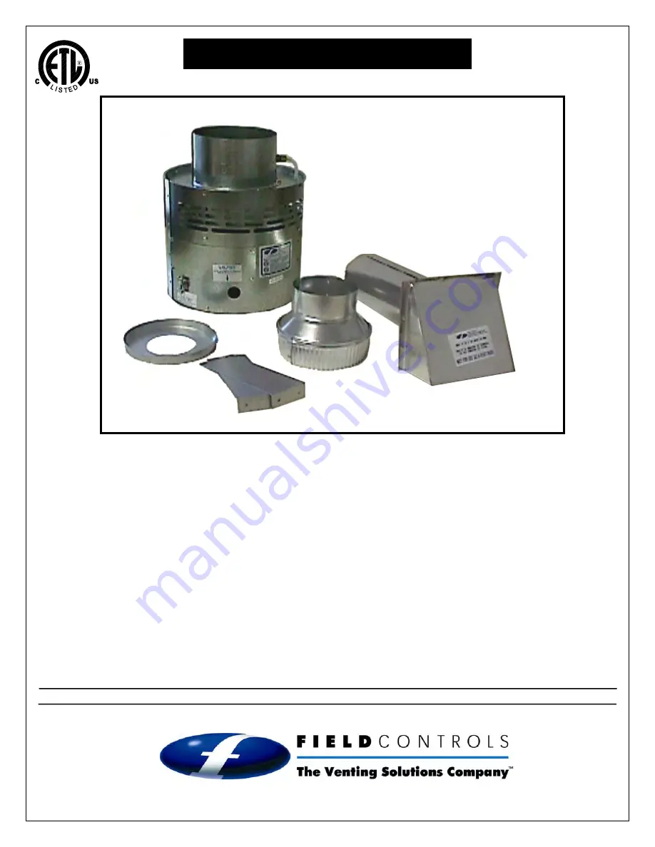
COMBUSTION AIR SYSTEM  

Model: CAS-4 


This product is designed for use with any natural gas or LP burning furnace, 
water heater, or boiler with a 24 VAC control system. It may be used with a 
millivolt powered system with additional hardware. It may also be used with 
more than one appliance. The CAS unit mechanically draws air into a 
structure and disperses it near the combustion air intake of an appliance. If an 
optional Vacuum Relief Valve (VRV) is used, the incoming air is tempered 
before entering the structure's airspace. Refer to Diagram A and B for 
guidance in setting up the CAS system based on the size and length of the 
connecting duct-work and the input rating of the appliance.


This device MUST be installed by a qualified agency in accordance with the manufacturers installation 
instructions.


The definition of a qualified agency is: 

any individual, firm, corporation or company which either in person or through a 

representative is engaged in, and is responsible for, the installation and operation of gas appliances, who is experienced 
in such work, familiar with all the precautions required, and has complied with the requirements of the authority having 
jurisdiction.


DO NOT DESTROY 

THESE INSTRUCTIONS MUST REMAIN WITH EQUIPMENT 


I

TEMS INCLUDED IN KIT

1) Motorized Blower 

1) 4" galvanized intake air Vent Hood 

2) Mounting brackets to secure the CAS to a wall 

2) Wire/conduit connector(s) 

1) 4" x 6" Pipe Increaser Fitting 

1) 6" Orifice Ring 

1) Instruction Sheet 

1) High/Low Motor Speed Switch


Summary of Contents for 46284600

Page 1: ...guidance in setting up the CAS system based on the size and length of the connecting duct work and the input rating of the appliance This device MUST be installed by a qualified agency in accordance...

Page 2: ...ould be used when installing the CAS system Using these charts will help ensure that the proper amount of air is drawn into the structure as needed by the appliance The defined regions shown correspon...

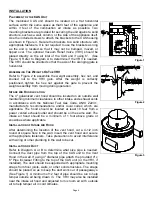
Page 3: ...iagonal line that says 4 inch Duct Hood Orifice Ring Therefore place the Orifice Ring into the inlet of the CAS so that it sits on the ledge above the fan It does not matter which way the Orifice Ring...

Page 4: ...FIRING RATE gallons per hour 1 gallon oil hr 140 000 BTU hr 6 Duct Hood 4 Duct Hood 4 Duct Hood Orifice Diagram A LOW SPEED SIZING CHART 0 50 100 150 200 250 300 0 50 100 150 200 250 300 350 400 GAS I...

Page 5: ...an outside wall maintaining minimum clearances to other intake and exhaust vents in accordance with the National Fuel Gas Code ANSI Z223 1 manufacturer s recommendations and or local codes which are...

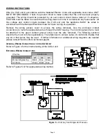
Page 6: ...ng terminals Use the enclosed conduit connector s to route the appropriate wires through the CAS housing The incoming ground wire must be attached to the green colored ground screw near the wire termi...

Page 7: ...Page 7 Figure 6 Power Vent Single 24V Furnace Figure 7 Chimney Vent 24V Furnace and 30mV Water Heater with CK 20FV or CK 20FG...

Page 8: ...Page 8 Figure 8 Chimney Vent 24V Boiler Figure 9 Power Vent Single 24V Boiler...

Page 9: ...Page 9 Figure 10 Chimney Vent Two 24V Gas Appliances With CAC 24...

Page 10: ...Page 10 Figure 11 One Power Venter Two 24V Gas Appliances With DIP 1...

Page 11: ...ove the top pan and clean the fan housing area as needed Reattach the top pan reconnect the duct pipe and the power supply REPLACEMENT PARTS The following items are available for replacement if needed...

Page 12: ...Page 12 PN 46284600 Rev G 10 06...

Reviews: