background image


Page 4

CONNECTING POWER VENTER TO APPLIANCE


The venting system should be installed and supported in accordance with the National Flue Gas Code, ANSI Z223.1, 
CGA Standards B149.1-M91, B149.2-M91, or in accordance with any local codes. A vent pipe connector shall be 
supported for the design and weight of the material employed, to maintain clearances, prevent physical damage and 
separation of joints. 
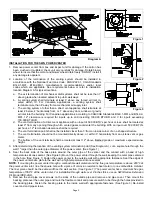
If mounting venting system near combustible materials, refer to Diagram B for allowable installation clearances. Always 
check local code requirements for code restrictions. 
Route the vent pipe from the appliance to the power venter using the minimum number of elbows necessary. The 
horizontal section of the vent pipe should have a slight upward slope from the appliance to the power venter. For 
clearances to combustible materials, multiple appliance venting, and other installation requirements, refer to the National 
Fuel Gas Code ANSI Z223.1, CGA Standards B149.1-M91, B149.2-M91, and/or any applicable local codes or appliance 
manufacturer's installation instructions. 

Table 3 

INSTALLATION CLEARANCE WITH SINGLE WALL VENT PIPE 

DOUBLE PIPE SYSTEM 

SINGLE PIPE VENTING SYSTEM 

Allowable Inlet Temperature 

Clearance (A) 

Allowable Inlet Temperature 

Clearance (A) 

400°F Or Less 

1/2” Minimum 

400°F Or Less 

1/2” Minimum 

400°F To 550°F 

1” Minimum 

400°F To 550°F 

1” Minimum 

400°F To 550°F 

1/2” Minimum 

With Sheet Metal Liner

400°F To 550°F 

1/2” Minimum 

With Sheet Metal Liner

NOTE:


Vent pipe joints should be secured with at least three sheet metal screws.


Use a PEK series extension kit or follow installation method below for a double pipe system. When the outer pipe of the 
SWG is extended over the inner pipe, use the double pipe guidelines for determining clearances. 

INSTALLATION USING TYPE B VENT PIPE


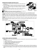
1.  Using a hand crimper or a like device, crimp the inner pipe of the SWG power 

venter approximately 1" long. (See Figure 4) 

2.  Attach the vent pipe over the crimped end of the SWG power venter inner pipe. 
3.  Secure the vent pipe to the SWG power venter inner pipe with at least (3) three 

#8 sheet metal screws. Pre-drilling the holes through both pipes will allow easi-
er fastening. 

Diagram B

Figure 4

Summary of Contents for 46334800

Page 1: ...e burner and allows the burner to fire 2 After the heating requirement has been satisfied the thermostat circuit will open and de activate the burner 3 The power venter operates for a period of time a...

Page 2: ...ensure appliance efficiency This should be done at the appliance exhaust outlet with a velocity meter or draft gauge 7 On gas fired furnaces a barometric draft control must be installed to regulate p...

Page 3: ...n point shall not be installed closer than 3 from an inside corner of an L shaped structure f The vent termination should not be mounted directly above or within 3 horizontally from an oil tank vent o...

Page 4: ...pplicable local codes or appliance manufacturer s installation instructions Table 3 INSTALLATION CLEARANCE WITH SINGLE WALL VENT PIPE DOUBLE PIPE SYSTEM SINGLE PIPE VENTING SYSTEM Allowable Inlet Temp...

Page 5: ...and fasten using sheet metal screws See Figure 7 2 If using a Type B Vent Tee the opening of the Tee at the draft control mounting location should be sealed with a high temperature sealant or equivale...

Page 6: ...turned to their original position and properly fastened The wiring should be protected by an over current circuit device rated at 15 amperes CAUTION Power venter wiring must not come in contact with a...

Page 7: ...repeat steps 5 through 7 as necessary until proper draft is obtained and the draft control gate is in the proper position 9 Tighten the damper locking screw on the SWG to prevent it from moving durin...

Page 8: ...rs so they operate at maximum speed Do not operate a summer exhaust fan 3 Place in operation the appliance being inspected Follow the lighting instructions and adjust thermostat so appliance will oper...

Page 9: ...ctions if necessary Check the Power Venter choke plate to insure it is secured in place Check the barometric draft control to insure the gate swings freely 4 System Safety Devices With the heating sys...

Page 10: ...Page 10...

Page 11: ...LER S NAME _____________________________________________________ INSTALLER S COMPANY _________________________________________________ INSTALLER S PHONE NO ____________________________________________...

Page 12: ...Page 12 P N 46334800 Rev A 11 00...

Reviews: