background image

GAS VENT DAMPER  

Model:

 GVD-4 through 12 

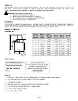
Field Controls (GVD) gas vent damper was developed to reduce off cycle venting losses through boilers and 
draft hoods.  When the boiler is in the standby mode heat escapes up the chimney. The heat comes from the 
boiler and the condition space. To significantly reduce these losses install a Field Gas Vent Damper. The 
damper is installed between the vent or chimney and as close to the draft hood as practical.  When properly 
installed the damper opens before the burner fires and closes after the burner shuts off. The electrical 
circuits in this product are designed not to override the existing limit and safety controls of the boiler. 


  CAUTION    


The plug is installed only if the 

appliance is equipped with an intermittent or direct 
ignition system. Failure to follow these instructions can 
cause odor problems and minor property damage due 
to moisture. Do not install on standing pilot systems.


Tape Plug 

Here 

English………..  Page 1 
Français………  Page 13


Summary of Contents for 46352700

Page 1: ...nt or chimney and as close to the draft hood as practical When properly installed the damper opens before the burner fires and closes after the burner shuts off The electrical circuits in this product...

Page 2: ...rmed prior to and during each heating season GENERAL INFORMATION DIMENSIONAL DATA ELECTRICAL DATA FEATURES 1 Service Switch Holds damper open and allows the appliance to operate without the damper ope...

Page 3: ...cable and without modification to the draft hood or the vent damper 8 Locate in a venting system or section of a venting system so that it services only the single appliance for which it is intended 9...

Page 4: ...by extinguishing the pilot burner s when the main burner s is off and determining after 3 minutes that the main burner gas does not flow upon a call for heat 11 a Visually determine that main burner...

Page 5: ...hookup with an added gas valve is shown in Diagram A Terminals one two and three must be the same polarity Failure to obtain correct polarity may damage the damper motor assembly To set the room ther...

Page 6: ...r between the draft hood and ventor chimney for the damper device See Figure 4 3 A minimum clearance of 6 inches between the device and combustible construction must be maintained and there must be pr...

Page 7: ...h a fused control circuit will not allow the burner to operated unless the vent damper is connected NOTE Internal fuse blow after the first complete cycle INSTALLATION ON EXISTING APPLIANCES This proc...

Page 8: ...s Turn on any exhaust fans such as range hoods and bathroom exhausts so they will operate at maximum speed Do not operate a summer exhaust fan Close fireplace dampers 11 Place appliance in operation F...

Page 9: ...olation relay is recommended This will eliminate possible erratic cycling of the damper the thermostat or the appliance controls Another option is to install a non power stealing type of thermostat Se...

Page 10: ...OWER Between 4 1 1 Off on limit 120VAC 2 Bad Transformer 3 Loose or broken connections 4 Blown fuse or circuit breaker 5 Disconnect switch off 6 Harness not plugged into appliance receptacle 1 Turn li...

Page 11: ...pressure control or low water cut off is on 3 Reset or replace blocked vent switch or flame roll out switch 4 Tighten repair or replace connection 5 Replace defective component in appliance Damper St...

Page 12: ...Page 12...

Page 13: ...fage le clapet du registre s ouvre avant la mise sous tension du circuit du br leur Si le clapet ne s ouvre pas le circuit de commande du br leur n est pas mis sous tension Install s convenablement le...

Page 14: ...les exigences des autorit s comp tentes en la mati re L entrepreneur qualifi doit inscrire son nom son adresse et la date de l installation sur l tiquette fix e au registre 2 viter de neutraliser le f...

Page 15: ...ection suivante vise permettre de d terminer si un appareil est correctement install et si son fonctionnement est s r Cette proc dure porte sur les installations centrales g n rateur de chaleur chaudi...

Page 16: ...ci pendant que le br leur principal est teint et en v rifiant apr s avoir laiss s couler 3 minutes s il y a arriv e de gaz cons cutive un appel de chauffage au br leur principal a S assurer que le gaz...

Page 17: ...reil 6 Diagramme A pr sente le branchement typique d un pilote avec un robinet de gaz additionnel Les bornes 1 2 et 3 doivent avoir la m me polarit afin de ne pas risquer d endommager le moteur du reg...

Page 18: ...tion ou la chemin e un endroit appropri pour l installation du registre Sch ma 4 3 Pr voir un d gagement minimum de 6 pouces entre le registre et toute construction combustible de m me qu un espace su...

Page 19: ...il n est pas branch sur le circuit NOTA Le fusible interne saute apr s le premier cycle complet INSTALLATION SUR UN APPAREIL DE CHAUFFAGE EXISTANT La proc dure suivante vise assurer l installation en...

Page 20: ...es portes de la pi ce dans laquelle se trouve l appareil et des autres pi ces de l immeuble sauf celles o se trouvent des ventilateurs d extraction Mettre en fonction s cheuses hottes de dessus de cui...

Page 21: ...re b Date de l installation C BLAGE Tous les accessoires lectriques utilis s et les travaux de nature lectrique r alis s dans le cadre de l installation du registre doivent se conformer aux codes d le...

Page 22: ...limentation 24 V c a Sous tension Position du registre 4 et 1 En permanence Ouvert ou ferm 4 et 1 Appel de chauffage Ouvert ou en cours 4 et 3 Pendant la combustion Ouvert PROBL ME CAUSE POSSIBLE SOLU...

Page 23: ...e 1 Ouvrir le robinet de gaz 2 Mettre le limiteur le r gulateur ou l interrupteur en fonction 3 R armer ou remplacer l interrupteur 4 Resserrer r parer ou remplacer la connexion 5 Remplacer l l ment d...

Page 24: ...Page 24 P N 46352700 Rev B 09 01...

Reviews: