background image


DIAGRAM A

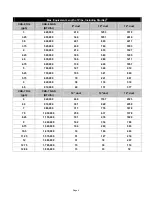
CAS-6 (FAN + STARKAP SK-10) SIZING CHART

MAX.  EQUIVALENT FEET OF PIPE 

0.0

25.0

50.0

75.0

100.0

125.0

150.0

175.0

200.0

400

600

800

1000

1200

INPUT FIRING RATE (BTU/H x 1000)

#2 OIL = 140,000 BTU/GALLON

E

Q

UIV

A

LE

NT LE

NGTH OF P

IP

E

 (ft.)

2.90

3.90

4.90

5.90

6.90

7.90

OIL INPUT FIRING RATE, GPH

12" 
PIPE

10" 
PIPE

6" 
PIPE

8" 
PIPE

6" DUCT 
REGION

8" DUCT 
REGION

10" DUCT 

REGION

12" DUCT

 REGION

Diagram A


DIAGRAM B

CAS-7 (FAN + STARKAP SK-12) SIZING CHART

MAX.  EQUIVALENT FEET OF PIPE 

0.0

25.0

50.0

75.0

100.0

125.0

150.0

175.0

200.0

800

1000

1200

1400

1600

1800

2000

INPUT FIRING RATE (BTU/H x 1000)

#2 OIL = 140,000 BTU/GALLON

EQUIVALENT LENGTH OF PIPE 

5.7

6.7

7.7

8.7

9.7

10.7

11.7

12.7

13.7

OIL INPUT FIRING RATE, GPH

12" 
PIPE

10" 
PIPE

8" PIPE

14" 
PIPE

8" DUCT 

REGION

10" DUCT 

REGION

12" DUCT 

REGION

14" 

DUCT

REGION

Diagram B


Page 3

Summary of Contents for 46371700

Page 1: ...gency in accordance with the manufacturers installation instructions The definition of a qualified agency is any individual firm corporation or company which either in person or through a representati...

Page 2: ...ng the horizontal axis and draw a vertical line through this point 5 The line should pass through at least one of the pipe size regions on the table The regions correspond to the maximum equivalent le...

Page 3: ...IPE 6 PIPE 8 PIPE 6 DUCT REGION 8 DUCT REGION 10 DUCT REGION 12 DUCT REGION Diagram A DIAGRAM B CAS 7 FAN STARKAP SK 12 SIZING CHART MAX EQUIVALENT FEET OF PIPE 0 0 25 0 50 0 75 0 100 0 125 0 150 0 17...

Page 4: ...9 424 1057 5 700 000 121 369 919 5 25 735 000 105 321 800 5 75 805 000 79 241 601 6 840 000 58 176 519 6 5 910 000 49 151 377 CAS 7 OIL gph CAS 7 GAS BTU hr 10 duct 12 duct 14 duct 6 840 000 469 1167...

Page 5: ...g pipe of different diameter than the CAS component connections attach increaser reducer fittings as close to the CAS unit and to the StarKap as possible The duct should be supported with appropriate...

Page 6: ...AS unit Refer to Figure 6 for connecting a single 120 VAC appliance to the CAS or Figure 7 for 24 VAC The three wires BURNER WHITE and ORANGE in Figure 4 correspond to the same wires shown in Figures...

Page 7: ...Figure 7 Figure 8 Page 7...

Page 8: ...Figure 9 Figure 10 Page 8...

Page 9: ...Figure 11 Figure 12 Page 9...

Page 10: ...ly CAUTION A minimum clearance of 1 must be maintained between the bottom of the fan blade and the top of the metal surface underneath FAILURE TO MAINTAIN THIS CLEARANCE MAY RESULT IN A FIRE HAZARD AN...

Page 11: ...Page 11...

Page 12: ...Page 12 P N 46371700 Rev B 06 06...

Reviews: