background image

COMBUSTION AIR SYSTEM  

Model

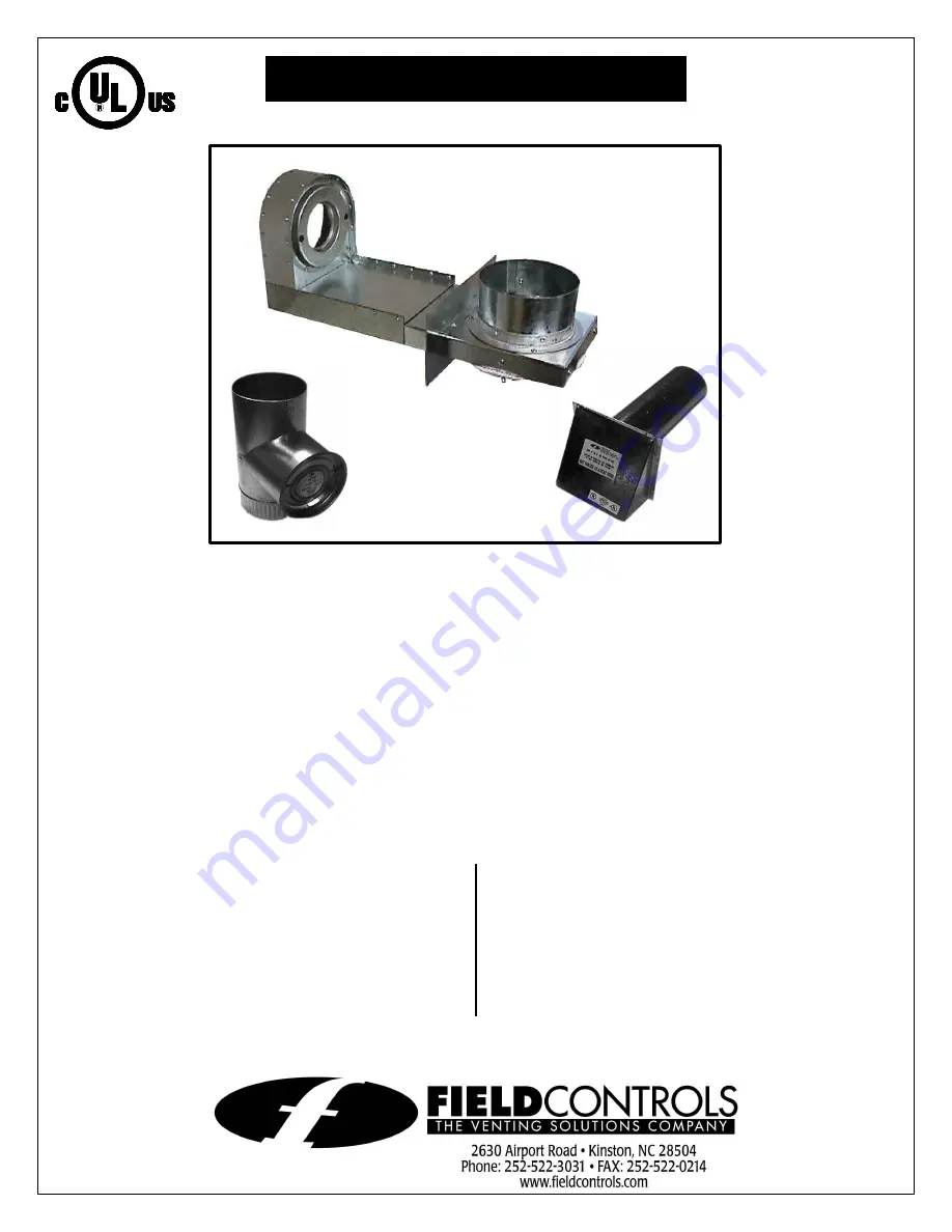
:  CAS-2B-90E Furnace Boot™ 

This product is designed for use on the Beckett AFG burners, 
for the purpose of routing combustion air directly to the 
burner, with the added safety feature of the vacuum relief 
valve.  

NOTE:


For burner inputs up to 1.5 gph at 100 psi input 

pressure or equivalent.


“The Furnace Boot™ model CAS-2B-90E is for use only on 
the designated burner(s) as described in these instructions 
only when the specific burner includes this Furnace Boot™ 
when shipped from the burner manufacturer or where the 
burner instructions specifically reference the model CAS-2B-
90E Furnace Boot™ as an optional air intake system.” 


I

TEMS INCLUDED IN KIT

1 - 90E Furnace Boot™ 
1 - Set of Gaskets 
1 - 4” VRV 
1 - 4” IAH Hood 
1 - Burner Coupling Set 
2 - Mounting Bolts 

I

NSTALLER SUPPLIED ITEMS

Duct Piping and Elbows 
90° Elbows; 
¼ “ NPT Female x ¼” NPT Male for 
routing oil line 


4” IAH 
HOOD 

4” VRV 


FURNACE 
BOOT™ 


Summary of Contents for 46381400

Page 1: ...s for use only on the designated burner s as described in these instructions only when the specific burner includes this Furnace Boot when shipped from the burner manufacturer or where the burner instructions specifically reference the model CAS 2B 90E Furnace Boot as an optional air intake system ITEMS INCLUDED IN KIT 1 90E Furnace Boot 1 Set of Gaskets 1 4 VRV 1 4 IAH Hood 1 Burner Coupling Set ...

Page 2: ...ain once the abnormal condition is corrected INSTALLATION 1 Before the Furnace Boot can be mounted a rectangular hole 2 X 6 must be located and cut into the side of the furnace cabinet The hole is located from the center of the burner intake See Figure 1 2 Remove the oil pump and air bands from the burner housing Install the sealing gaskets onto the burner housing See Figure 2 Replace existing pum...

Page 3: ...y in Then attach lock nut and knurl nut See Figure 7 6 Mount the VRV assembly onto the tee and fasten with a screw and nut in collar tabs To ensure proper operation check the gate for being level across the pivot points and plumb See Figure 8 7 Refer to Figure 9 for general installation layout TERMINATION LOCATION GUIDELINES 1 Mount intake hood 12 inches above finished grade If mounting on the sid...

Page 4: ...ocal codes 4 To reduce uncontrolled air leakage into the duct tape all joints and seams using standard duct tape NOTE To prevent sweating on the outside of the duct when operating in areas that have 10 F or below design temperatures insulate the duct work at least 10 feet from the inlet vent termination OPERATION AIR ADJUSTMENT 1 Adjust the air adjustment knob on the side of the Furnace Boot See T...

Reviews: