background image

page 11 of 12

ITEM DESCRIPTION

FIELD PART NUMBER

Motorized Fan

46274100

Pressure Switch Fxd for CAS-4TMR

511100200

24 VAC Relay for CAS-4

46161400

120 VAC Relay for CAS-3,4

46257300

MAINTENANCE

1.  Inspect the system annually to ensure proper operation by observing that the fan activates when a call for 

heat occurs and deactivates when the call for heat is satisfi ed.

2.  Disconnect power to the CAS unit and repeat Step 1. Note: The unit should not run and the appliance 

should not fi re in this condition.

3.  Inspect the duct pipe for cracks and security to the CAS unit and vent hood.  The CAS unit will not allow 

the appliance(s) to fi re if inadequate air fl ow is allowed into the inlet of the CAS.

4.  Clear any obstructions, if present, from the inlet of the vent hood and the outlet of the CAS unit.

5.  Periodically, the fan blade chamber may need cleaning. First, disconnect the power supply to the CAS. 

Next, disconnect the duct pipe from the unit. Then remove the top pan and clean the fan housing area as 
needed. Reattach the top pan, reconnect the duct pipe and the power supply.

REPLACEMENT PARTS

The following items are available for replacement, if needed. In order to replace these parts, power must be 
disconnected and the unit must be disassembled. If this is necessary, take note of the positions and locations 
of whatever items that may need to be removed to replace other items. 

If in doubt, please consult Field Controls Technical Support at 1-800-742-8368.

P/N 46284600 Rev L 09/19

Summary of Contents for FAN IN A CAN CAS4

Page 1: ...24 control kit per each additional appliance see note The CAS unit mechanically draws air into a structure and disperses it near the combustion air intake of an appliance Refer to Diagrams A and B fo...

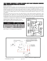
Page 2: ...l within one of the three regions on the table Each region corresponds to a duct pipe diameter of 4 4 using the orifice ring and 6 respectively GENERAL SYSTEM OPERATION 1 The thermostat wall thermosta...

Page 3: ...matter which way the Orifice Ring is turned as long as it is pushed down against the ledge completely Use 4 diameter pipe to connect the vent hood and the CAS unit TOTAL INPUT OF APPLIANCE TOTAL INPU...

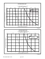
Page 4: ...00 250 300 350 400 GAS INPUT FIRING RATE 1000 BTU hr MAX EQUIVALENT DUCT LENGTH ft 0 0 0 50 1 00 1 50 2 00 2 50 OIL INPUT FIRING RATE gallons per hour 1 gallon oil hr 140 000 BTU hr 6 Duct Hood 4 Duct...

Page 5: ...a power vented exhaust outlet and should be on the same wall The intake air hood should be a minimum of 1 above grade or snowlines where applicable INSTALLATION OF INTAKE AIR HOOD After determining t...

Page 6: ...be attached to the green colored ground screw near the wire terminals The following sections describe the most common applications The references to various series of control kits implies that any ki...

Page 7: ...page 7 of 12 Figure 5 Power Vent Single 24V Furnace Figure 6 Chimney Vent 24V Furnace and 30mV Water Heater With CK 20FV or CK 20FG P N 46284600 Rev L 09 19...

Page 8: ...page 8 of 12 Figure 7 Chimney Vent 24V Boiler Figure 8 Power Vent Single 24V Boiler P N 46284600 Rev L 09 19...

Page 9: ...page 9 of 12 Figure 9 Chimney Vent Two 24V Gas Appliances With CAC 24 P N 46284600 Rev L 09 19...

Page 10: ...page 10 of 12 Figure 10 One Power Venter Two 24V Gas Appliances P N 46284600 Rev L 09 19...

Page 11: ...nadequate air flow is allowed into the inlet of the CAS 4 Clear any obstructions if present from the inlet of the vent hood and the outlet of the CAS unit 5 Periodically the fan blade chamber may need...

Page 12: ...ed and printed from the Field Controls website www fieldcontrols com WARRANTY WARRANTY For warranty information about this or any Field Controls product visit For warranty information about this or an...

Reviews: