background image

29

Air Flow Balancing using the Door Ports

FC155HRV & FC200HRV only

Door balancing ports (not on all models) are designed to be used in

conjunction with a Magnehelic Gauge or Digital Manometer to
measure the Stale and Fresh airflows for balancing.

Step 1

Prepare the air flow measuring device (i.e. Magnehelic Gauge or

Digital Manometer) by connecting the hoses to the low and high

pressure side of the gauge.

Step 2

Insert the hoses into the rubber fittings from the optional Door Port

Adapter Kit (part # 99-182). Use light pressure and rotate until

fitting is snug. Do not extend the hose past the rubber fitting.

Step 3

Open the HRV Door. Remove the 4 Door Port Covers by carefully

pushing them out from the back side of the door (use the blunt end

of a large drill bit etc.).

Step 4

Close the HRV Door. Initiate power and operate the HRV on high

speed. Operate the forced air system on high speed (if the HRV is

connected to the forced air system) .

Step 5

Insert the 2 rubber fittings from the gauge to the STALE AIR

Balancing Ports (upper right and lower left). Seal the FRESH AIR

Balancing Ports (upper left and lower right) with tape. Record your

reading.

Step 6

Insert the 2 rubber fittings from the gauge to the FRESH AIR

Balancing Ports (upper left and lower right). Seal the STALE AIR

Balancing Ports (upper right and lower left) with tape. Record your

reading.

Step 7

Refer to the "Airflow Reference Chart" for your model and

determine the FRESH AIR and STALE AIR flow rates (the chart is

located on the lower portion of this page).

Step 8

Damper down the higher airflow and repeat Steps 5 to 7 as required

until both airflows are identical (balanced).

Step 9

Remove the tape and rubber fittings and reinstall the 4 Door Port

Covers.

MODEL 200

0 230

153

156

Manometer

Reading

Airflow Numbers

(CFM)

(in. w.g.)

0.100

98

91

0.110

102

96

0.120

107

101

0.130

111

107

0.140

115

112

0.150

120

117

0.160

124

122

0.170

128

127

0.180

133

132

0.190

137

137

0.200

141

142

0.210

145

147

0.220

149

152

0 230

.

153

156

0.240

157

161

0.250

161

166

0.260

165

171

0.270

169

175

0.280

173

180

0.290

177

184

0.300

181

189

0.310

185

193

0.320

189

198

0.330

192

202

0.340

196

207

0.350

200

211

0.360

203

215

MODEL 155

0 180

142

129

Airflow Numbers

(CFM)

Pressure

(in. w.g.)

Fresh Air Stale Air

0.100

93

80

0.105

96

83

0.110

99

86

0.115

102

89

0.120

105

92

0.125

108

96

0.130

111

99

0.135

114

102

0.140

117

105

0.145

120

108

0.150

123

111

0.160

130

117

0.170

136

123

0 180

.

142

129

0.190

148

135

0.200

154

141

0.210

160

147

0.220

166

154

0.230

172

160

0.240

178

166

0.250

184

172

0.260

191

178

0.270

197

184

0.280

203

190

0.290

209

196

0.300

215

202

0.310

221

209

Pressure

Manometer

Reading

Fresh Air Stale Air

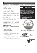
Magnehelic Gauge hoses connected to

STALE AIR balancing ports

Illustration of measuring STALE airflow using a Magnehelic Gauge.

Magnehelic Gauge hoses connected to

FRESH AIR balancing ports

Illustration of measuring FRESH airflow using a Magnehelic Gauge.

Fresh Air
Balancing Ports
(top-left,
bottom-right)

Stale Air
Balancing Ports
(top-right,
bottom-left)

Illustration of a door with door ports

Airflow Reference Charts

FC200HRV

FC155HRV

All manuals and user guides at all-guides.com

Summary of Contents for FC150ERV Operation and

Page 1: ...ct earned the ENERGY STAR by meeting strict energy efficiency guidelines set by Natural Resources Canada and the US EPA It meets ENERGY STAR requirements only when used in Canada FC95HRV FC155HRV FC20...

Page 2: ...r handler operating at a higher static After installation the compatibility of the two pieces of equipment must be confirmed by measuring the air flows of the HRV by using the balancing procedure foun...

Page 3: ...trol instructions located in the Operation and Installation Manual for instructions on how to set the dehumidistat The dehumidistat function on the main control should be set to OFF for all seasons ex...

Page 4: ...atic setting The Dehumidistat should be set to OFF for all seasons except the heating season Dehumidistat Part DH1 Healthy Home System Control HHSC Dehumidistat Indicator LEDs Set to the desired humid...

Page 5: ...ls Never use the dehumidistat feature when outdoor temperatures are above 59 F 15 C Setting the Dehumidistat Press and release the DEHUMIDISTAT button until the DEHUMIDISTAT LED is at the desired sett...

Page 6: ...ts indicate high speed operation Lockout Mode is useful if you wish to disable the timer Set lockout by holding the Select Button for 5 seconds Unlock by holding for 5 seconds Optional Vent Timer Cont...

Page 7: ...the access door will fit tight against the core 4 Motors Maintenance Free 5 Drain condensate Line Clean once a year Inspect drain line drain spout and P trap for blockage mould or kinks Flush with wa...

Page 8: ...s Date ___________________________________________ Tag _____________________Qty ___________________ Project _________________________________________ Engineer _______________________________________ C...

Page 9: ...Air Flow Stale air enters the FRONT RIGHT side port The air passes down the front half of the core then up the back half of the core and out the RIGHT REAR port Fresh outdoor air enters the LEFT REAR...

Page 10: ...___________________________ Tag _____________________Qty ___________________ Project _________________________________________ Engineer _______________________________________ Contractor _____________...

Page 11: ...___________________________________ Supplier ________________________________________ Quote _________________________________________ Submitted by ____________________________________ Sensible Efficie...

Page 12: ...30 L s 32 F 0 C 81 Sensible Efficiency 64 cfm 30 L s 32 F 0 C 69 Total Efficiency 50 64 cfm 30L s 95 F 35 C 47 VAC 60HZ 120 WATTS Low speed 63 WATTS High speed 173 Amp rating 1 4 LATENT RECOVERY MOIST...

Page 13: ...stale air duct should have a timer which will initiate high speed ventilation Refer to Optional Timers in this manual Fresh air ducts should be installed to all bedrooms and living areas excluding bat...

Page 14: ...R 40 1m MINIMUM Outdoors Cool Air Return 3 min recommended Forced Air Furnace Dampers for balancing airflows Backdraft Damper Leaf Hinge Simplified Installation Diagrams Simplified Installation Return...

Page 15: ...e HRV is in standby OFF or Recirculate WARNING Partially Dedicated Installation Diagrams Partially Dedicated System This installation enables stale air to be drawn from the poorest air quality areas o...

Page 16: ...equired Kitchens if required Fresh air to house main living areas bedrooms livingroom rec room etc Fully Dedicated Installation Diagrams Fully Dedicated System This is a stand alone HRV ERV system whi...

Page 17: ...rvice agency WARNING Unit must be installed level to ensure proper condensate drainage Due to the broad range of installation and operational conditions consider the possibility of condensation formin...

Page 18: ...e ceiling Kitchen Exhaust grilles must never be connected to the range hood They should be installed at least 4 feet 1 2 m horizontally away from the stove Field supplied balancing dampers should be i...

Page 19: ...g Do not locate in a garage attic or crawl space Exhaust Weatherhood Requirements At least 6 2 m from the ventilation air intake At least 18 460 mm above ground or above the depth of expected snow acc...

Page 20: ...re Retainer located on the Back Plate Figure C 8 Attach the Back Plate to the wall using the 2 supplied screws and anchors 9 Attach the Face Plate to the Back Plate Figure B Note Be careful to correct...

Page 21: ...uring lockout mode the High Speed Status Light will momentarily illuminate but no override will be initiated If lockout mode is initiated when the timer is activated the timer will continue its timed...

Page 22: ...stallation or turning the unit on 7 Push any excess wire into wall and against mounting base 8 Snap cover onto base while ensuring pins align with sockets in connector 9 Once powered the HHSC automati...

Page 23: ...RING TERMINALS 12V 24 VAC Field wiring 20 AWG min required Connect V Terminal on the HHSC Control to the Hi Terminal instead of Lo for a shorter ventilation period Setting up the HHSC Control The dura...

Page 24: ...a shorter ventilation period One DH 1 Dehumidistat and or one or more VTC timer controls may be connected as shown Connect all Red Yellow and Green control terminals to the corresponding HRV ERV termi...

Page 25: ...ed Connect V Terminal on the HHSC Control to the Hi Terminal instead of Lo for a shorter ventilation period One DH 1 Dehumidistat and or one or more VTC timer controls may be connected as shown Connec...

Page 26: ...HRV ERV will be fully off when the OFF position is selected on the Main Control Timers and or other controls will not function when the HRV ERV is in the OFF position The fully off feature can be modi...

Page 27: ...Prior to balancing the unit first adjust air flows in branch lines to specific areas of the house If the outdoor temperature is below 0 C 32 F ensure the unit is not running in defrost Place the magn...

Page 28: ...and damper down the duct with the highest duct velocity pressure Repeat Step 2 and Step 3 until both ducts show indentical readings For this example the Fresh Air to Building air stream has the highe...

Page 29: ...s located on the lower portion of this page Step 8 Damper down the higher airflow and repeat Steps 5 to 7 as required until both airflows are identical balanced Step 9 Remove the tape and rubber fitti...

Page 30: ...is due to the high return static pressures found in some furnace installations The FC155HRV and FC200HRV models have factory installed Balancing Dampers located in the Fresh Air to Building and Stale...

Page 31: ...of the HRV have contractor balance HRV locate the grilles high on the walls or under the baseboards install ceiling mounted diffuser or grilles so as not to directly spill the supply air on the occup...

Page 32: ...re IMPORTANT Control low voltage is 12 24VAC DO NOT CONNECT EXTERNAL POWER SOURCES TO THE UNIT DEFROST DETAILS Not Applicable to FC150ERV P1 1 2 3 4 PIN 1 BLACK PIN 2 ORANGE PIN 3 RED PIN 4 SPARE PCB...

Reviews: