background image

www.fi eldcontrols.com

Please retain these instructions after installation.

This device MUST be installed by a qualifi ed agency in accordance with the manufacturer's installation instructions. The defi nition of 
a qualifi ed agency is: any individual, fi rm, corporation or company which either in person or through a representative is engaged 
in, and is responsible for, the installation and operation of HVAC appliances, who is experienced in such work, familiar with all the 
precautions required, and has complied with all the requirements of the authority having jurisdiction.

READ THESE INSTRUCTIONS CAREFULLY AND COMPLETELY BEFORE PROCEEDING WITH THE INSTALLATION.

Installation Date:

Installed By:

Phone:

POWER VENTER

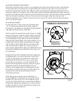
Model: PVE Series

CONTENTS

Page

Typical Venting System Components...............................................

System Operation..............................................................................

Power Venter Sizing...........................................................................

Installation Safety Instructions..........................................................

Installation of Power Venter...............................................................

Connecting Power Venter to Appliance..........................................

General Wiring Instructions..............................................................

Airfl ow 

Adjustments..........................................................................

General Installation Inspection.........................................................

M aintenance. . . . . . . . . . . . . . . . . . . . . . . . . . . . . . . . . . . . . . . . . . . . . . . . . . . . . . . . . . . . . . . . . . . . . .

Replacement 

Parts List.......................................................................

System Operational Information......................................................

2

3

3,4

5,6

6,7

7

7

8

8,9

9,10

10

11

Summary of Contents for PVE-100

Page 1: ...amiliar with all the precautions required and has complied with all the requirements of the authority having jurisdiction READ THESE INSTRUCTIONS CAREFULLY AND COMPLETELY BEFORE PROCEEDING WITH THE IN...

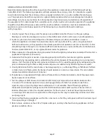
Page 2: ...ng as the reducers and specific size pipe are considered when deter mining equivalent length of vent pipe Figure 1 DESCRIPTION OF POWER VENTER MODELS SWH 1 3 3 SWH 1 4 4 SWH 1 5 5 SWH 1 6 6 SWH 1 8 8...

Page 3: ...h a 24 VAC gas valve Includes an adjustable post purge relay timer and a draft control for draft induced appliances Use the CK 43F for a non adjustable post purge relay timer Use the CK 44F for draft...

Page 4: ...330 900 000 180 290 1 000 000 125 190 1 250 000 80 EQUIVALENT LENGTH FEET OF VENT PIPE FOR VENT PIPE FITTINGS Vent Pipe Fittings Vent Pipe Diameter 3 4 5 6 7 8 9 10 TEE 19 25 31 38 44 50 56 63 90 ELB...

Page 5: ...or gas appliances and Class L Type Vent Pipe for oil appliances Refer to national or local codes for guidelines 5 Disconnect power supply before making wiring connections to prevent electrical shock a...

Page 6: ...o public walkways b A venting system shall terminate at least 3 above any forced air inlet located within 10 c The venting system of other than a direct vent appliance shall terminate at least 4 below...

Page 7: ...ake Within 10 Feet SWG Vente At Le Insid SWG SERIES POWER VENTER INSTALLATION LOCATIONS Diagram A PVE Sidewall Vent Termination Locations GENERAL WIRING INSTRUCTIONS The PVE 100 300 600 and 1200 are d...

Page 8: ...on Inspection to check for negative pressure problems in the building Refer to the appropriate control kit installation instructions for pressure switch adjustment procedure and system checkout proced...

Page 9: ...n burner operation at low flame 7 Test for spillage at draft hood or barometric draft control opening and burner inlet air location after 5 minutes of main burner operation Use a draft gauge flame of...

Page 10: ...heck the barometric draft control if installed to ensure the gate swings freely 4 System Safety Devices With the heating system operating disconnect the pressure sensing tube from the pressure switch...

Page 11: ..._______ CO Measurement _________________________________________________________________________ Equipment Outlet Flue Gas Temperature________________________________________________________ FOR OIL F...

Page 12: ...hone 252 522 3031 Fax 252 522 0214 www fieldcontrols com Field Controls LLC P N 46115300 Rev F 04 15 WARRANTY For warranty about this or any Field Controls product visit www fieldcontrols com warranty...

Reviews: