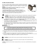
SIDEWALL POWER VENT
Model:
SWG-AF Series
*Patented
Field Controls SWG-AF series power vents
TYPICAL VENTING SYSTEM COMPONENTS
1 – SWG-AF or SWG-VR-AF Series Power Vent
1 – RC Draft Control (Required Accessory Not Included)
1 – WMO-1 blocked vent switch (Required Accessory Not Included)
1 – DIP-1 pressure switch (Required Accessory Not Included)
WARNING:
The Field Controls SWG-AF series power vent system must be installed by a
qualified agency in accordance with the appliance manufacturer’s installation instructions.
The definition of a qualified agency is: “.. any individual, firm, corporation, or company who either in
person or through a representative is engaged in, and is responsible for installation and operation of
solid or bio-fuel burning heating appliances. Who is experienced in such work, familiar with all the
precautions required, and has complied with the requirements of the authority having jurisdiction”.
WARNING:
Read the installation instructions carefully and completely before proceeding with the
installation.
For continued safe operation, the appliance vent system combination is required to be
cleaned, inspected and maintained annually by a qualified agency.
Failure to properly maintain the appliance vent system combination can lead to Death,
Personal Injury and or Property Damage.
A Carbon Monoxide alarm
MUST
be installed when venting
solid or Bio-Fuel heating
appliances. Refer to the appliance manufacturer’s installation instructions.
The Field Controls DIP-1 pressure switch, Barometric Draft Control and WMO-1 blocked vent
switch must be properly installed and interlocked to the appliance burner feed circuit.
The SWG-AF power vent and draft equipment is only for use as a venting option for specific
listed automatic fuel-burning appliances. Refer to the appliance manufacturer’s instructions for
proper application, wiring and installation.
DO NOT DESTROY
THESE INSTRUCTIONS MUST REMAIN WITH EQUIPMENT
Summary of Contents for SWG-AF Series
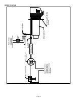
Page 10: ...Page 10 WIRING DIAGRAM...
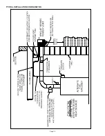
Page 15: ...Page 15 TYPICAL INSTALLATION CONFIGURATION...
Page 17: ...Page 17...
Page 35: ...Page 17...


