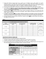
Page 5
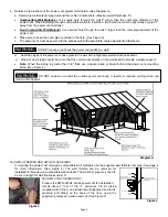
4. Determine the location of the power vent system termination. (See Diagram A)
a. Determine wall material type Combustible or Non Combustible. (Maximum wall thickness: 8”)
Combustible Wall Material:
cut a square hole through the wall 2" larger than the outer pipe diameter of the
power vent. When installing through combustible wall with insulation, the insulation must be physically secured 1”
away from the power vent wall liner.
Non Combustible Wall Material
: Cut a square hole through the wall 1” larger than the outer pipe diameter of the
power vent.
b. Make sure to keep the outer pipe centered in the hole. (See Figure 6)
c. The power vent must be secured to the outside wall with appropriate coated weatherized fasteners.
d. Seal the edges of the power vent base plate to the wall with a high temperature silicone sealant.
e. Wood or vinyl siding should be cut so that the unit mounts directly on the wall board to provide a stable support.
Note:
When the siding is greater than 1/2" thick use a spacer plate or board behind the power vent mounting
base. (See Figure 2)
5a) SWG-AF SERIES AND SWG-VR-AF SERIES
If mounting the power vent through a combustible wall materials use the supplied wall thimble liner pipe. See page 4
for more information. (See Figure 6) The wall thimble can be removed for
installations through non-combustible wall material. The wall liner pipe may need to
be cut to length for wall thickness under 8”.
5b) SWG-VR-AF SERIES ONLY
Prepare the SWG-VR-AF series power vent for installation:
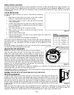
Uncoil about 2 feet of the ¼” aluminum CK kit tubing
(supplied with CK kit), and attach the straightened end to the
pressure port fitting on the back of the riser, using the
supplied compression sleeve and nut. (See Figure 3)
Figure 3
Diagram A
Figure 2
WARNING:
DO NOT enclose or restrict the outside power vent body. It results in reduced cooling which can
create a fire hazard!
WARNING:
DO NOT recess or set back the power vent outlet in a wall!
Summary of Contents for SWG-AF Series
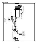
Page 10: ...Page 10 WIRING DIAGRAM...
Page 15: ...Page 15 TYPICAL INSTALLATION CONFIGURATION...
Page 17: ...Page 17...
Page 35: ...Page 17...


