page 10 of 16
INSTALLATION: WIRING & CONTROLS
The fi nal step in this fan’s installation is to install its controls. The VentCool 1.8 unit can be equipped with two
different control packages: 1st generation or 2nd generation. Either control package works the same with
controlling the operation of the fan. The standard control package included with this fan contains: the control box,
1 wall switch, 1 mounting bracket for the wall switch, and 50 ft. of red CAT5 cable.
First, locate the control box. The control box is an 12.375” x 5.5” x 2.0” galvanized steel electrical box. It is connected
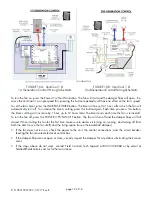
to the fan assembly and has a series of RJ45 ports on one side. These ports are labeled with the following label (refer
to Figures 12A or 12B, depending if unit is equipped with either 1st or 2nd Generation control package):
The green FAN, white WEB and yellow AUX ports are not used by this fan.
Connect the red CAT5 cable to the red W/S
W/S port located on the electrical control box on the \fan
housing. Then, run the cable through the attic and down the wall to the desired location for the wall switch
d down the wall to the desired location for the wall switch
(Refer to Figure 13A or 13B for additional wall switch nomenclature). Note: This cable is low-voltage but unshielded.
(Refer to Figure 13A or 13B for additional wall switch nomenclature). Note: This cable is low-voltage but unshielded.
Building Codes require unshielded low-voltage wiring to be run through shielded conduit. Do not run cable in
Building Codes require unshielded low-voltage wiring to be run through shielded conduit. Do not run cable in
parallel with 110V or greater wiring.
parallel with 110V or greater wiring.
Connect the included wall switch to the fan’s control box regardless of whether or not it will be
h to the fan’s control box regardless of whether or not it will be
installed in a wall.
installed in a wall.
Because an accessible wall switch is necessary for providing technical support, this
Because an accessible wall switch is necessary for providing technical support, this
switch MUST be installed.
switch MUST be installed. FAILURE TO INSTALL THE WALL SWITCH WILL VOID THIS FAN’S WARRANTY!
FAILURE TO INSTALL THE WALL SWITCH WILL VOID THIS FAN’S WARRANTY!
If it is not desired to be installed in a wall, connect the switch to the control box’s red W/S port and leave it stored in
the attic with the cable kept spooled.
FIGURE 12A: Electrical Control Box Port Labeling - 1st Generation Control Package
FIGURE 13A:
1st Generation Wall Switch
FIGURE 13B:
2nd Generation Wall Switch
INCREASE TIMER
FAN OFF
START FAN
BUTTON DOES
NOTHING
FIGURE 12B: Electrical Control Box Port Labeling - 2nd Generation Control Package
WALL SWITCH INSTALLATION:
(Refer to Figure 12A or 12B for Electrical Control Box Port
Labeling)
P/N 78010007000 05/17 Rev B

