background image

page 12 of 16

To turn the fan on, press the POWER ON / SPEED UP button. The fan is programmed to start on its lowest speed
setting. To increase the fan’s speed, press this button again: its speed will increase to the next higher setting.
Pressing this button repeatedly will incrementally increase the fan’s speed until it reaches its highest setting. 

To decrease the fan’s speed, press the SPEED DOWN button. The fan’s speed will decrease to the next lower setting. 
Pressing this button repeatedly will incrementally decrease the fan’s speed until it reaches its lowest setting.

The following instructions for operating this fan have also been provided in the “

How to Operate Your Whole 

House Fan

” document included with this fan.

Before starting this fan for the fi rst time, verify that:
1.  All wiring and connections have been made according to this manual and acceptable wiring standards, and that 

this manual and all local codes and standards have been followed in this fan’s installation;

2.  No tools or construction debris have been left in, on, or around the fan; and,
3.  Plug the unit power cord into a 120 VAC outlet. Werify ON/OFF Breaker switch on electrical control box is ON. 

Turn ON power to 120 VAC outlet.

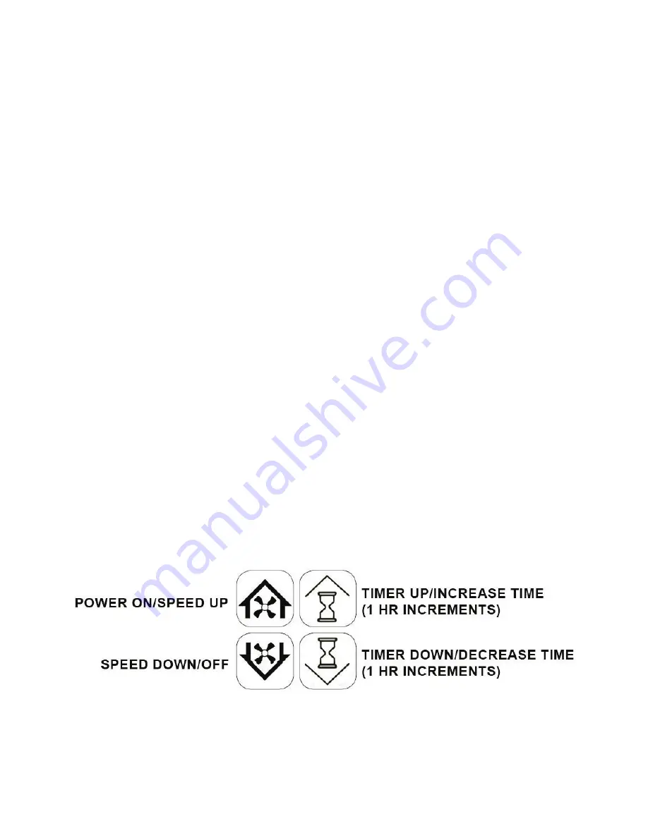
Each of this fan’s control interfaces (the hardwired wall switch or wireless remote) looks and operates the same: 
There are four buttons that turn the fan on or off, increase or decrease its speed, and set its timer. The appearance of 
these buttons is shown in the illustration below. (See Figure 17)

START-UP & OPERATION

To merge a remote control transmitter and receiver, follow these steps:

1.  Remove the receiver’s top cover.

2.  On the receiver’s circuit board, locate the black button labeled LEARN. Press and release this button to 

begin the merge sequence; the RJ45 port’s yellow transmission LED will illuminate.

3. Immediately

 press and release any button on the wireless transmitter while the transmission LED is 


illuminated. If the merge is successful, the transmission LED will turn off.

4.  Repeat steps 2 and 3 if there are any additional remote control transmitters to merge with the receiver.

5.  Replace the receiver’s top cover.

A wireless remote is an available accessory for this fan. It is not included as part of the ventCool standard control 

package. 

To install a wireless remote with this fan, fi rst mount the wireless remote receiver on an attic joist near the control 

box using wood screws and the pre-drilled mounting holes. Connect one end of the blue CAT5 cable provided with 

the remote control kit to the receiver’s RJ45 port. Then, run the cable to the fan’s control box and connect its free 

end to the blue RMT port.

Field Controls remote control transmitters and receivers are pre-merged at our factory. They may, however, become 

unmerged prior to installation. A remote control transimitter that has become unmerged from its receiver will not 

be able to control the fan. In this case, the transmitter and reciever will need to be remerged.

WIRELESS REMOTE (OPTIONAL)

FIGURE 17:  Control Button Nomenclature

P/N 780100500 05/19 Rev B

Summary of Contents for VentCool 2.4

Page 1: ... Fan assembly with electrical control box Duct tape 30 ft 7ft ofacousticallyinsulatedflexduct 20 diameter 20 ft of 1 polypropylene webbing AirLoc Gravity Backdraft Damper Backdraft Damper Transition Collar and Phillips head screws 12 Fan Collar White Cube Core Grille White Phillips head screws 8 Wood screws 8 Control Package including Control box Wall Switch with Mounting Bracket and Orange CAT 5 ...

Page 2: ...ng Before installing this fan inspect it and all of its parts for any damage it may have sustained during shipping DO NOT INSTALL DAMAGED EQUIPMENT shipping DO NOT INSTALL DAMAGED EQUIPMENT If you suspect this fan has been damaged during shipping contact Field Controls technical support by phone at 1 800 742 8368 or email at fieldtec fieldcontrols com Whole House Fans are designed to be installed ...

Page 3: ...r switch and a 10 ft power cord measured from the elec trical control box to power cord plug end Consider this length when choosing a location for this fan to be mounted Depending on the location of existing outlets in the attic the installation of an additional outlet may be required Consult an electrician if necessary All wiring and connections must be made according to this manual and acceptabl...

Page 4: ...st properly constructed homes have adequately ventilated attics not all do Because sufficient ventilation is so critical to this fan s performance it is important that the home s existing ventilation be verified before it is installed Since most attics have multiple vents often of different types it is necessary to count each vent noting its type and s ize Then apply the appropriate ratio to each ...

Page 5: ...s far greater when the surrounding environment is quiet such as within a bedroom at night Within the attic locating the fan near an electrical outlet or power supply can minimize the need for additional electrical work The first step in installing this fan is to build a simple box between the framing in the ceiling and to create an opening into the attic The fan s backdraft damper has been designe...

Page 6: ...urther please make sure to pass the fan assembly backdraft damper transition collar and ductwork through the opening created in the previous step and into the attic These subcomponents have been designed to fit through the clear opening Since they may not fit through the attic s crawl hole they must be in the attic before proceeding further Once in the attic verify the backdraft damper collar is i...

Page 7: ...stalled with the Y axis at a slight angle However this angle must NOT exceed 45 as shown in Figure 6C The X axis must NEVER be installed at any angle as The X axis must NEVER be installed at any angle as shown in figures 7A and 7B Installing the backdraft shown in figures 7A and 7B Installing the backdraft damper outside of these constraints will prevent its doors damper outside of these constrain...

Page 8: ...otion Ensure that the fan is as level as possible Keep the area in front of the fan as unobstructed as possible At the least the nearest object obstructing the path of fan s exhaust airflow can be no closer than 24 to the face of the fan Attach the fan cone to the fan assembly for VentCool 3 5 4 9 models The fasteners necessary to connect the fan cone to fan housing are preinstalled in the fan hou...

Page 9: ...ported under the bend using the pro vided polypropylene webbing The webbing can be attached to the rafters using wood screws nails or staples Fold over the end of the webbing at the attachment point so that the screw nail or staple is securing it to the rafter through 2 layers Once the fan assembly is balanced and secure use the provided duct tape to seal the joints between the ductwork and the ba...

Page 10: ...upport this switch MUST be installed support this switch MUST be installed FAILURE TO INSTALL THE HARDWIRED WALL SWITCH WILL VOID FAILURE TO INSTALL THE HARDWIRED WALL SWITCH WILL VOID THIS FAN S WARRANTY THIS FAN S WARRANTY FIGURE 12 RJ45 Port Labels on Electrical Control Box Using the provided wall mounting bracket Figure 14 as a template trace an outline on the wall where you would like the swi...

Page 11: ... Switch DIP Switch Settings Rear Surface of Display Switch Figure 16 shows the generic wiring schematic of the VentCool 2 4 3 4 and 4 9 units FIGURE 16 VentCool 2 4 3 4 4 9 Wiring Diagram P N 78030007034 P N 780100500 05 19 Rev B ...

Page 12: ...ttons is shown in the illustration below See Figure 17 START UP OPERATION To merge a remote control transmitter and receiver follow these steps 1 Remove the receiver s top cover 2 On the receiver s circuit board locate the black button labeled LEARN Press and release this button to begin the merge sequence the RJ45 port s yellow transmission LED will illuminate 3 Immediately press and release any ...

Page 13: ...expensively conditioned or heated air out of the home We recommend running this fan through the night Here s why The goal of using a whole house fan is to cool the entire home not just the air inside it Once heated the home s structure and contents continue to radiate heat until reaching the temperature of the surrounding air Running this fan through the night speeds up this cooling process and ca...

Page 14: ... Due to our continual product improvement efforts performance ratings and specifications are subject to change without notice TABLE 1 TABLE 2 Air flow and sound is influenced by installation duct alignment and air door angle Some models of ventCool are shipped with 1 3 HP ECM Motors P N 780100500 05 19 Rev B ...

Page 15: ...page 15 of 16 Figure 18 Spare Parts P N 780100500 05 19 Rev B ...

Page 16: ...ARRANTY WARRANTY For warranty information about this or any Field Controls product visit For warranty information about this or any Field Controls product visit www fieldcontrols com ventCool www fieldcontrols com ventCool page16of16 Field Controls Technical Support Field Controls Technical Support 1 800 742 8368 1 800 742 8368 fieldtec fieldcontrols com fieldtec fieldcontrols com Phone 252 522 30...

Reviews: