


Field of View GeoSnap Basic Manual 16
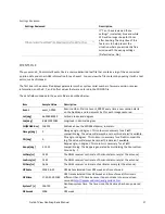
Offsets
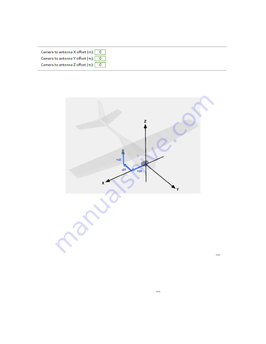
Camera to Antenna Offsets
Description
Type in the X, Y, and Z offsets from the camera to the
antenna. More information on how to do this correctly is
below.
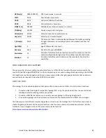
This diagram show how the X, Y, and Z axis aligned to an airframe. It also shows that an offset may be positive or
negative depending on where the antenna is mounted relative to the camera.
The simple, fast way to determine the offsets when using the GeoSnap is to follow these steps:
1)
Use a tape measure or ruler to estimate the X and Y offset from the lens centerline to the center of the
antenna. A rough estimate (+/- 2cm) is sufficient since any error in the X and Y offset measurements tend
to get averaged to near 0 when performing grid mapping missions. Keep in mind that the all the offsets
need to be entered into the CONFIG file in meters.
2)
The Z offset is more critical to measure accurately. Add the following distances to get the Z offset value
when using the GeoSnap
dZ =
antenna L1 phase center-to-bottom of antenna
+ bottom of antenna-to-focal plane mark( o ) of the
lens focal length
For the grey helical antenna that is included with most GeoSnap kits, the distance from the antenna L1
phase center to the bottom of the antenna is 0.0318 meters. The resulting equation would be:
dZ =
0.0318 meters
+ bottom of antenna-to-focal plane mark( o ) of the lens focal length


