Page of 15
13
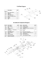
Pull
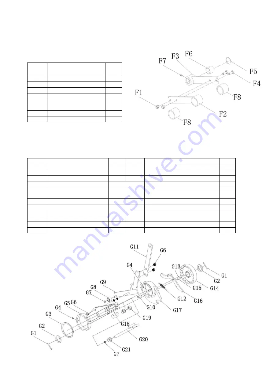
Plate Diagram
Part #
Description
QTY
F1
Hex Lock Nut M10
2
F2
Sleeve A
1
F3
Sleeve B
1
F4
Hex bolt M10*25
2
F5
Steel Cable Baffle Ring
1
F6
Bush
1
F7
Oil zerk
1
F8
Pipe
2
Intermittent Components
Diagram
Part #
Description
QTY
Part #
Description
QTY
G1
Cotter Ø5*45
2
G12
Tension spring
1
G2
Flat
2
G13
Cotter Ø2*16
1
G3
Shaft ring Ø110
1
G14
Intermittent driving components
1
G4
Oil zerk
2
G15
Flat key
1
G5
Intermittent transmission
component
1
G16
Hook
1
G6
Hex Lock Nut M10
2
G17
Eccentric component
1
G7
Shaft ring Ø12
1
G18
Round pin of transmission rod
1
G8
Wheel
1
G19
Hex Nut M18
2
G9
Control Handle
1
G20
Transmission rod
1
G10
Round pin Ø12*30
1
G21
Transmission rod base
1
G11
Handle component
1


