background image

EN 

1

Use and operation

FDB

P


200951-E

Carefully unpack and inspect your sander. Fully familiarise yourself 
with all functions/features of the tool


Ensure that all parts of your sander are present and in good 

condition. If any part is missing, or damaged, have such parts 

replaced before attempting to use this tool. Always use dust 

extraction where available, or a dust bag where not

Fitting


sanding


belts

WARNING: 

Before fitting sanding belts, ensure that the sander is 

disconnected from the power supply. 


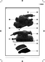
To fit a new sanding belt, first remove the Depth Frame (12), if fitted


Place the sander upside down on a workbench or similar solid, flat surface

Pull out the Belt Release Lever (11). This retracts the Front Roller (10) 

and slackens the sanding belt. The worn belt can now be removed

Fit the new sanding belt, positioning it squarely over the rollers


Close the belt release lever. The belt should now be taut and secure


Once fitted, it may be necessary to adjust the front 

roller to ensure that the belt runs true

Keep the sander inverted on the work bench, and connect it to power


Hold the sander firmly by the Rear Handle (3) and depress the On/Off 

Trigger (8). Observe any sideways motion of the belt

 If needed, turn the Belt Tracking Adjuster (7) clockwise to move the belt 

left, or anti-clockwise to move the belt right until the belt runs true

Disconnect the sander from power

Fitting


the


depth


frame

The Depth Frame (12) allows you to control the depth of material removal 

and helps avoid tilting and gouging

 Ensure the sander is disconnected from power

Place the sander upside down on a workbench or similar solid, flat surface


 Position the Depth Frame (12) so that it is about half way along the 

thread of the Depth Adjustment Knob (13)

Summary of Contents for FDBP 200951-E

Page 1: ...FDBP 200951 E...

Page 2: ...3 A...

Page 3: ...ONTENTS PICTORIAL APPENDIX 3 GENERAL SAFETY INSTRUCTIONS 4 Important Safety Instructions Package Instruction Manual SYMBOLS 5 MACHINE DESCRIPTION AND ITEMS DELIVERED 6 GENERAL SAFETY INSTRUCTIONS 6 SP...

Page 4: ...SYMBOLS Double insulated Read the Instruction Manual attentively prior to use The product complies with the applicable standards and regulations Use eyes protective equipment Use ears protectiove equi...

Page 5: ...t to abide by and adhere to the following safety instructions for reasons of protection against injury caused by electric current injury of persons and risk of starting fires The term power tools used...

Page 6: ...r touch power tools with wet hands Never wash power tools with running water and never submerse them into water Do not use the power cord for any other purpose than originally intended Never carry or...

Page 7: ...firmly and keep your balance Work only in places that you can reach safely Never overestimate your own strength Do not use power tools if you are tired Dress appropriately Use working clothes Do not...

Page 8: ...ore easily controlled Using other accessories than those listed in the instruction manual can cause damage to the tool and can cause injury Use power tools accessories work tools etc in accordance wit...

Page 9: ...ied in this manual there is a risk of injury Angle grinder conforms to applicable technical regulations and standards These electro mechanical tools are intended for use as grinder It is necessary to...

Page 10: ...the insulated holding surfaces Contact of the tool with a live wire can cause the metallic parts of the electromechanical tool to become live and may cause an injury by electric current Mobile power s...

Page 11: ...y throw the operators arm away Do not stand in the area into which the tool might be thrown by the kick back Kick back will throw the tool in the opposite direction to the movement of the disk at the...

Page 12: ...now be removed Fit the new sanding belt positioning it squarely over the rollers Close the belt release lever The belt should now be taut and secure Once fitted it may be necessary to adjust the front...

Page 13: ...on To start the machine squeeze the On Off Trigger 8 To stop the machine release the trigger For extended continuous use you can lock the on off trigger in the on position 1 Squeeze the on off trigger...

Page 14: ...thework surface To avoid unnecessary damage to the work surface keep the movement direction of the sanding belt parallel with the natural grain of the wood 4 Move the sander slowly across the surface...

Page 15: ...tor may become worn Excessively worn brushes may cause loss of power intermittent failure or visible sparking A spare pair of brushes is supplied with this tool To replace the brushes remove the Brush...

Page 16: ...d amending Directive No 95 16 EC The Directive of the European Parliament and the Council No 2002 95 EC dated 27 January 2003 on the restriction of the use of certain hazardous substances in electrica...

Page 17: ...1 8 m LpA sound pressure level 92 3 dB A LwA sound power level 103 3 dB A Vibration level ah D1 2 316 ms 2 K 1 5 ms 2 Instructions Manual language version only Amendments to text and technical paramet...

Page 18: ...lectrical defect to the product 1 1 Connect to power supply 1 2 Check by a specialist electrician 1 3 Check by a specialist electrician 2 Product does not reach full power 2 1 Extension cord is not su...

Page 19: ...uy an equivalent new product By dutiful disposal of this product you can preserve precious natural resources and you help prevent any potential adverse effects on the environment and human health whic...

Reviews: