EN
ELECTRIC STRING TRIMMER
USER'S MANUAL
9
5. ASSEMBLY
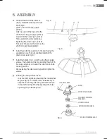
Connect the shaft of the trimmer
(Fig 2). Insert the bottom part of the
shaft (Fig 2,
point 1) into the coupling (Fig 2,
point 2),
which is a part of the top part of the
shaft. The locking pin (Fig 2, point 3)
must fi t into the hole (Fig 2, point 4).
Then secure both parts in place by
tightening the screw (Fig 2, point 5).
For easier transport of the trimmer, the
shaft can again be separated.
Install the protective guard on to the shaft using the
supplied screws. The nuts are integrated into the
plastic cover (see Fig. 3).
Install the handle (Fig 1, point 5) using the included
screws. The handle can be moved along the shaft. In
this way, everybody can select the ideal comfortable
working position.
After selecting the ideal working position, tighten the
screws.
Installing the string trimmer head.
- Lock the shaft in place by inserting the included hex
key (see Fig. 4). To achieve this, it is necessary to
align the hole in the protective guard with the hole
in the shaft and insert the hex key. Align the holes
by turning the protective guard.
Assembly
Fig. 2
Fig. 3
RETAINING WASHER B
Fig. 4
HEX KEY 4 MM
SHAFT
PROTECTIVE COVER
COGGED RETAINING
WASHER A
LOCKING HOLE
STRING TRIMMER HEAD
Summary of Contents for FZS 2050-E
Page 1: ...EN ...
Page 17: ...EN 18 FZS 2050 E Notes ...


