11
OPERATION MANUAL
GASOLINE BRUSH CUTTER
EN
Machine assembly
4. MACHINE ASSEMBLY
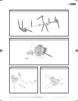
Drive shaft parts
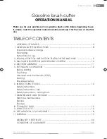
Drive shaft assembly
(see Fig.2)
Unscrew hexagonal screws (M6 x 10; Figs. 2, 1) .
Fasten the drive shaft to the engine housing with the help of 4 screws, tighten thoroughly.
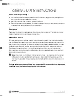
Handle assembly
(see Figs. 3, 4, 5)
Unscrew screws (2), put the handle bars to the grip holder (1), select the position according
to your working style (right-handed – the switch on the right side when viewing from the
engine). Pre-screw the upper parts of the grip holder (4 screws) (2), adjust the position of the
handle bars and tighten the screws (2) thoroughly.
Gearbox parts
(see Figs. 6, 7)
Unscrew the locking bolt, mount the cutting tool respectively (see Fig. 6): Gearbox (1) –
Cutting head carrier (2) – Cutting blade (3) – Cover (4) – Fixing nut (5). Insert a screwdriver
to align the gearbox body groove with a hole of the cutting head carrier.Tighten the nut with
the aid of the tubular spanner (6) delivered within the packaging.
Note:
Instead of the cutting blade, you can wind the head with the cord on the screw of the
carrier.
Mount the safety cover (3) on the shaft rod with the help of a clamp (2) and screws (1). Be
particular about the proper position (see Fig. 7
Cord replacement
(see Figs. 13, 14, 15, 16)
Demount the cord head, take-out the coil with the cord and remove the rest of the cord.
Pull a new cord of the total length c. 2 m through both openings in the inner part of the cord
head (see Fig. 14) so that both ends are of the same length (see Fig. 13).
Wind both ends onto the coil in the direction of the WIND CORD marked arrow (see Fig. 15).
Place the coil with the cord into the head (see Fig. 16), pull both ends of the cord through the
opposite openings in the head and finish the assembly (close up).


