EN
12
FZS 5025-B
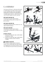
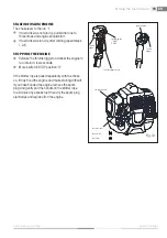
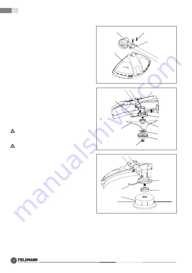
INSTALLING PLASTIC SHIELD
Install the safety cover on the shaft with the safety
cover bracket and the screws provided. Tighten the
screws after setting the safety cover bracket at the
appropriate position.
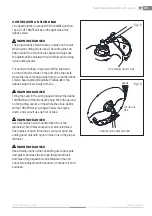
BLADE INSTALLATION
-
Insert the hex key (2) into the specifi c hole in the
angle transmission (3) and rotate the nut (7)
by hand until the hex key enters the inner hole ,
blocking rotation.
-
unscrew the nut (7) in a clockwise direction.
-
Pull out blade cover (6) and the blade press
board(5).
-
Ensure that the grooves in the key gasket (4)
mach up perfectly with the angle transmisson(3).
-
Install the blade (1) and the blade press board(5).
-
Refi t the blade cover (6) and the nut (7),fully
tightening it in an anticlockwise direction.
-
Remove the hex key (2).
WARNING CAUTION
Do not use a steel blade for edging or scalping.
WARNING CAUTION
EXCESSIVE VIBRATION- STOP ENGINE IMMEDIATELY
Excessive vibration of blade means that it is not
properly installed. Stop engine immediately and check
blade.
Blade improperly installed will cause injury. Use only
our company original cutting equipment parts when
servicing and repairing the unit.
HEAD LINE INSTALLATION
Insert the hex key (2) into the specifi c hole in the angle
transmission (3) and rotate the key gasket (4) by
hand until the hex key enters the inner hole, blocking
rotation.
-
Ensure that the grooves in the key gasket (4).
mach up perfectly with the angle transmisson(3).
-
Fit the cutting line head (1) screwing it up in an
anticlockwise direction. (see from cutting line
head).
-
Remove the hex key (2).
Assembly
Fig. 4
Fig. 5
1
2
3
4
Fig. 6
M6×20 SCREWS
GEAR CASE
BRACKET
SHIELD

