background image

       Hydraulic 

Post Driver 

Models: Farmer, Fencer and Forte 

Issue date: July 2012 


OWNERS /OPERATORS MANUAL 

AND SPARE PARTS LIST 


Summary of Contents for Farmer

Page 1: ...Hydraulic Post Driver Models Farmer Fencer and Forte Issue date July 2012 OWNERS OPERATORS MANUAL AND SPARE PARTS LIST ...

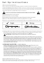
Page 2: ...s Spend sufficient time to familiarise yourself and other users with all set up operation and maintenance instructions and recommendations to ensure your own safety and the efficient long term use of this implement Always use genuine FIELDMASTER parts for any spares or replacement components needed in your maintenance or repairs ...

Page 3: ...mount of oil back to the tractor Fitting of a QRC coupling will pressurize the return hose and most likely BURST under pressure The return hose is specifically specified and fitted from the factory as a LOW PRESSURE return line 3 4 and must have NO restriction back to the tractor 8 OPEN CIRCUIT VALVE SYSTEM standard configuration If you have a Closed Circuit System on your tractor a modification o...

Page 4: ...wn the mast b Hammer stops with a soft cushioned stop rather than bounce if it stops with a bounce the port relief is set too tight and will not be working Port relief valve Pt No 116025 03 Item 1 Valve control lever kits refer to parts dept for spares available Handle kit pt number 116025 01 Item 2 Port relief valve Pt No 116025 03 Item 3 Rear blanking plug to remove for closed circuit valve bung...

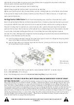
Page 5: ...chine 5 Connect chain from the post cap to the prong on the hammer weight and raise the weight up by pulling the lever backward see direction of arrow on valve 6 Position the post cap so that the top of the post is directly underneath the post cap spike Always position the post cap spike directly in the centre of the post 7 Lower the weight so that the locator spike holds the post securely and rem...

Page 6: ... all three legs are touching the ground 4 Disconnect the pressure hydraulic supply hose and then the return hose 5 Slackenoffthetoplinkandremovethehitchpin EnsurethatthePostDriverisinastableposition 6 Remove the hitch pins from the plough arms 7 Check that nothing is connected to the tractor before driving off 8 WhenPostDriverisdisconnectedfromthetractor donotleavefreestanding Tieorchainmastuphigh...

Page 7: ...replace 8 Examine all Hydraulic Hoses and couplings for leaks cracks and damage Repair or replace 9 Examine all Bolts and Pins Check for tightness wear and possible failure If worn replace if evident 10 Examine all moving parts Repair or replace as required if any parts appear worn broken or twisted 11 Check all Clamps and couplings on Wire Rope For looseness or damage replace all worn or damaged ...

Page 8: ...right and tractor cab rear window is clear of folding arc 5 Fold mast carefully keeping well clear of moving mast 6 Fit locking pin in transport position for safety and stability during transport storage To Raise 1 Remove locking pin from transport position 2 Ensure mast is full upright so mast arc is clear of tractor cab 3 Raise slowly ensuring wire rope is clear of obstruction to full height 4 R...

Page 9: ...e spike hole by raising the hammer 9 Lower the hammer down moving the spike point away from the spike hole 10 Release the Supa Spike chain from over the hammer and lift the spike back into the RHS cradle on the leg of the post driver Instructions for operating Hydraulic Rock Spike Extractor unit 1 Raise hammer and postcap carefully to just above rock spike height 2 90mm or 120mm spike is carried s...

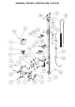
Page 10: ...FARMER FENCER CONTRACTOR FORTE ...

Page 11: ...026 Hydraulic Control Bank 4B 116027 Hydraulic Control Bank SB 116031 Hydraulic Control Bank 6B 20 116600 01 Valve Mount Bracket 116605 Bulls eyeLevel self adhesive ITEMNO PARTNO DESCRIPTION 21 715036 01 Main Lift Ram 4m Mast N S 715056 Seal Kit for Main Ram 1 1 4 spear Old Type 715056 01 SealkitforMainRam 2 spear Std 23 1173 Hose Mount Clamp Set 25 116012 Wire Rope Pulleys 9x 28 B2070 Top Pulley ...

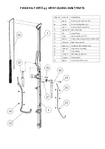
Page 12: ...ding Mast Top Section 22 999005 02 Main ram hose 23 1173 Hose Clamp 24 10040 Main Ram Mount Pin 26 B20130 Pulley Mounting Bolt Nut M20x1 30 27 116602 02 Mast Fold Lock Pin 32 998001 01 Hydraulic Ram Mast Fold 33 1998007 Hose Kit for Fold Ram 34 1177 Hose Clamp 35 715037 01 Main Ram 4 5 Mast 715056 01 Ram Seal Kit 36 840015 Wire Rope Kit for 4 5m ...

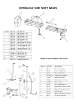
Page 13: ...5 Aluminium tool tray 900 4 998004 01 Sideshift ram 600 998004 03 Sideshift ram 300 998004 04 Sideshift ram 900 5 10015 4 way MPS ram 5a 998005 4 way MPS hose kit 6 A8245 01L Storage parking stand ITEM NO PART NO DESCRIPTION 1 A8242 90mm rockspike pin 1a A8243 120mm rockspike pin 2 36005 Nylon ring for spike 3 34014 34015 Locking device brackets 4 715038 Main extractor ram 4a 715038 01 Seal kit fo...

Page 14: ...c Relief valveseatdamagedduetooil Leakingportreliefvalveisduetocontaminated contamination dirtyoilfromtractor thisisnotawarranty problem Pleasereplacetractoroilfilter NotEnoughangleorsidetilt Sometractorsarefittedwithlong shortlinkagearms thusmakingthelengthofthetoplinkraminsufficient Contactyour Fieldmaster dealer as you can purchase a top link and side tilt extensionbrackettoenable extendedlengt...

Page 15: ......

Page 16: ......

Reviews: