S e t U p I n s t r u c t i o n s
1)
Bolt on valve mounting handle bracket.
2)
Bolt on hydraulic control bank (using fastenings provided) to the underside of valve mounting bracket.
3) FENCER & FARMER MODEL WITH HYDRAULIC OPTIONS -
for safety these models are fitted with a transport/locking bar
over the side angle ram. Retain this in position and ensure there is oil in the system before lifting to the vertical position.
This ensures the mast will stay upright. Safety bar may now be removed.
FAILURE TO DO THIS MAY RESULT IN PERSONAL INJURY OR DAMAGE TO THE POST DRIVER.
4)
Attach storage leg, lift mast to vertical position.
5)
Attach the Post driver to tractor 3 Pt linkage.
6)
Set the Hydraulic port relief on the hammer valve: (see detailed “setting the Port relief valve’ section below)
a)
Before use, Check carefully all hydraulic connections are tight and have no oil leaks.
b)
Check all 3 x wire rope grips (beside hyd. ram) are tight, and the hammer is securely fastened to the wire rope correctly.
7) Attach single QRC to tractor remote and dump hose to hydraulic return tank. Tank end of dump hose is fitted with a ¾
BSP female nut. Use this to attach to your oil return tank. Different size thread adaptors may be needed to suit your
tractor – a fitting pack of popular sizes is available from Fieldmaster: Part no 999005.01
NOTE
:
DO NOT use a QRC fitting on the return/ dump hose connection to the tractor.
Fitting a QRC (Quick release coupling) restricts the oil flow that has to be fed back into the tank. When the
hammer is dropped (while driving posts) the return/dump hose has to cope with a very high / fast flow of oil
as the hammer is lowered under speed and requires a fast exit of a large amount of oil back to the tractor.
Fitting of a QRC coupling will pressurize the return hose and most likely BURST under pressure. The return
hose is specifically specified and fitted from the factory as a “LOW PRESSURE” return line (3/4”) and must
have NO restriction back to the tractor.
8)
OPEN CIRCUIT VALVE SYSTEM:
– standard configuration
If you have a “Closed Circuit System” on your tractor, a modification or
upgrade
fitting kit is required (Kit part number 116025.02)
The standard configuration of the Rammer control valve is an ‘Open circuit’ system.
If your tractor has a closed circuit hydraulic system, this means the oil system from the tractor requires a continuous
flow of oil to go through the Rammer valve and back to the tractor (as the tractor won’t have its own ‘bypass valve’ to
send the oil back to the tank when the Rammer valve is not being used or is idle, (usually known as oil supply ON
DEMAND which means that the tractor would only supply oil as the Rammer valve needs it). In this case, if your tractor
has a closed circuit hydraulic system, you will need to fit the closed circuit modification kit (Part number 116025.02)
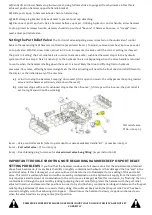
which comprises of a small bung that is to be fitted into the port which is located underneath the hex head blanking
plug on the side of the valve (see diagram next page). To fit this “Closed circuit plug” you will need to remove the
outer hex blanking plug (as shown) and screw in the ¼” BSP Bung - right in, then replace the Hex blanking plug again.
This will now allow the ‘Tank Pressure’ to be the same as the ‘Input Pressure’ on the Rammer valve and work in
conjunction with your ‘Closed circuit tractor hydraulic’ system.
9)
Remove storage leg & bracket. Put to one side.
10)
Place hammer on approximately 300mm high block, pallet, etc. Manoeuvre tractor & post driver over top of
hammer. (Locate mast in channel of hammer). Lower post driver on to hammer. Attach wire rope.

