background image


When driving on roads, the implement must be in transport position,  adequately  raised  
from  the road surface, with tractor lifting hydraulics locked so that the implement cannot 
be lowered accidentally. 


  DANGER 

The implement may be wider than the tractor. Pay attention to transporting for people, 
animals, buildings/sheds and/or other obstacles. 

  WARNING 

When turning, use extreme care and reduce tractor speed. 

  WARNING 

Do not operate the tractor with weak or faulty brakes or worn tires. 

  CAUTION 

Always use tractor lighting system and auxiliary lighting system for an adequate warning to 
operators of other vehicles, especially when transporting at night or in conditions of 
reduced visibility. 

  DANGER 

In the case of lifting this implement, make sure that any lifting device is suitable to perform 
the operation safely, and use only the lifting points prescribed on Rotary Hoe. 


1.5.


MAINTENANCE SAFETY INSTRUCTIONS 

  WARNING 

All maintenance and repair operations must be performed by qualified and trained 
operators, with the tractor engine off, the PTO disengaged, the implement lowered to the 
ground or on security stands, the ignition key off and the parking brake set. 

  WARNING 

Perform repairs and replacements part should only be original spare parts provided by the 
manufacturer, importer or your dealer. 

  DANGER 

Perform maintenance operations using appropriate Personal Protective Equipment 
(protective eyeglasses, hard hat, hearing protection, safety shoes, overall and work gloves, 
filter mask). 

  CAUTION 

Summary of Contents for SABRE 1200

Page 1: ...SABRE 1200 1500 ROTARY SLASHER TOPPER Models SABRE OWNERS OPERATORS MANUAL AND SPARE PARTS LIST ...

Page 2: ... will allow you to understand this new piece of equipment and will provide you all the tools needed to use it safely Proper maintenance and knowledge of the safety rules of use will ensure the best performance and extend the life of the machine The Safety Alert Symbol used throughout this manual and on safety decals of the machine indicates the presence of potential hazard to the operator When you...

Page 3: ...tion and may not reflect the product in the future The Manufacturer reserve the right to make design improvements or changes in specifications without incurring any obligation to install them on units previously sold Text illustrations and drawings of this manual cannot be disclosed or transmitted in whole or in part to third parties without the written permission of the Manufacturer All rights ar...

Page 4: ...ictograms are legible If pictograms are worn they must be replaced with others obtained from the Manufacturer and placed in the position indicated by this manual DANGER Before using the machine make sure that all safety devices are installed and in good working conditions In case of damages of shields replace them immediately DANGER Is absolutely forbidden to remove or alter safety devices DANGER ...

Page 5: ...e lighting system of the tractor and possibly an auxiliary lighting system 1 2 EQUIPMENT SAFETY INSTRUCTIONS WARNING Use the implement for its intended purpose only Improper use can damage the implement and cause serious injury to persons animals or death DANGER The machine should be used by a single operator driving the tractor WARNING Any unauthorized modification of the machine may cause proble...

Page 6: ... weight tractor implement and ballast is on the front axle of the tractor to ensure stability Add front ballast if required WARNING Before engaging the tractor PTO make sure the tractor PTO speed is set as required for this implement 540 rpm or 1000rpm Do not over speed PTO or machine breakage may result DANGER Do not operate the implement if the driveshaft is damaged The driveshaft could break du...

Page 7: ...e power take off to avoid damage to the machine DANGER In presence of steep slopes the action of this machine may cause instability of the tractor with a risk of tipping off which a consequence may be serious injury or death hazard Consult the manual for the tractor to determine the maximum slope that the tractor is able to deal with DANGER Always disengage the PTO before raising the implement and...

Page 8: ...g and wearing caused by too long or frequent slipping of the clutch since it can damage the clutch components Before checking the clutch make sure it has cooled Clutch could be extremely hot and cause a severe burn CAUTION Prolonged use of the implement can cause overheating of the gearbox Do not touch the gearbox during use and immediately after it could be extremely hot and cause a severe burn W...

Page 9: ...ight or in conditions of reduced visibility DANGER In the case of lifting this implement make sure that any lifting device is suitable to perform the operation safely and use only the lifting points prescribed on Rotary Hoe 1 5 MAINTENANCE SAFETY INSTRUCTIONS WARNING All maintenance and repair operations must be performed by qualified and trained operators with the tractor engine off the PTO disen...

Page 10: ...g the operation or before unhooking the implement stop the tractor set the brakes disengage the PTO lower the attached implement to the ground shut off the engine remove the ignition key and wait for all moving parts to stop WARNING Make sure all parked machines are on a hard level surface and engage all safety devices CAUTION Place support blocks under implement as needed to prevent the unit from...

Page 11: ...for oil leaks from the gearbox or the transmission side cover Identify the reason of loss then repair and or replace the damaged components check the correct oil level in the gearboxes check that blades are not excessively worn and the relating hardware is correctly tightened check that all hardware nuts bolts etc are properly tightened check that all safety decals are correctly positioned in good...

Page 12: ...h size model you have purchased lower the implement on the ground and simultaneously start driving the tractor forward at low speed Subsequently increase the ground speed depending on ground conditions If the outside temperature is very cold it s recommended to engage the PTO and have the implement operate at low speed with the tractor stationary to warm oil and lubricate parts Drive for a while o...

Page 13: ...ly attached Replace if any irregularily or excessive wear shows Fitting to the Tractor The mower is attached to the tractor three point linkage in normal manner The telescopic drive shaft can then be fitted Fit stabiliser bars or chain Fit the drive shaft securely to the tractor P T O and gearbox input shaft Ensure that both splined yokes are securely fastened to the splined shaft on both the trac...

Page 14: ... the height of the cut 1 By adjusting the skids in relation to mowing deck 2 By adjusting the rear roller or wheels in relation to the mowing deck and skids if fitted 3 By adjusting both the roller assembly or wheels separately if fitted in relation to the mowing deck to give a wide range of roller to skids positioning in conjunction with altering the height of cut It is important to set your FIEL...

Page 15: ...he shaft is fitted to the machine or tractor a simple test should be carried out On raising and lowering the machine fully on the linkage arm at no point of time should the P T O shaft be fully compressed During the raise and lowering travel when the P T O shaft is at the shortest length allowance should be made for the shaft to compress a further 40mm but taking care that the shaft is not cut too...

Page 16: ... tend to bed in after the first 10 15 hours and must be checked Check all oil levels driveshaft grease universal joints roller and wheel bearings Check main hub holding flail blade carrier to gearbox is tightened as this is a taper spline shaft that also takes some bedding in and must be tightened At the end of the mowing season we request that you call your Fieldmaster agent to have an out of sea...

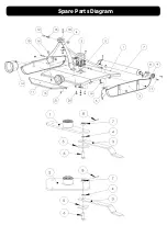
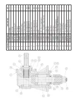
Page 17: ...Spare Parts Diagram ...

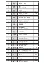
Page 18: ... Pin Cat 1 2 11 147024 Front or Rear Guard 1200 optional 1 147029 Front or Rear Guard 1500 optional 1 12 5040 Top Link Pin Cat 1 1 13 5040 01 Washers Top Link Pin 2 14 21904 02 PTO Cone For Clutch Option 1 15 21901 PTO Cone Std 1 FST PTO Cone Mounting Bolt M8 x 16 2 16 FST M16 x 40 Bolt Nylock Washers 2 17 FST M16 x 60 Bolt Nylock Washers 4 18 FST M16 x 50 Bolt Nylock Washers 3 19 FST M12 x 40 Bol...

Page 19: ... 0 20 1 11 08 005A Output Gasket 0 30 VAR 12 08 005B Output Gasket 0 13 VAR 13 07 001 FST 10 14 06 008 3 8 16 X 1 Cap Screen 10 15 11 008 1 14 Slotter Flange Hex Nut 1 16 12 003 Cotter Pin 1 17 15 001 Blade Hub 1 18 5 04 105 33 Output Seal 1 19 20 003 Output Cap 1 20 10 002 Output Bearing Spacer 1 21 03 004 15 Tooth Output Sft Pinion 1 22 4 03 104 02 Ball Bearing 207 1 23 09 002 1 2 Oil Fill Plug ...

Page 20: ......

Page 21: ......

Page 22: ...to the original user Manufacturer shall not be liable for loss damage or expense directly or indirectly from the use of its product or from any other cause Defective parts must be returned freight paid each way by the purchaser to the manufacturer This warranty shall not apply to any parts which must be replaced because of normal wear or which have been subject to misuse negligence or accident or ...

Reviews: