background image

18

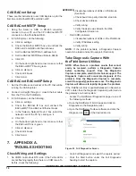
CAS BACnet Setup

These are the instructions to set CAS Explorer up for the 

first time on BACnet MS/ST and BACnet/IP.

CAS BACnet MS/TP Setup

1.  Using  the  Serial  or  USB  to  RS-485  converter, 

connect it to your PC and the 3 Pin BACnet MS/TP 

connector on the ProtoNode RER.

2.  In CAS Explorer, do the following:

a.  Click on settings.
b.  Check the BACnet MSTP box and uncheck the 

BACnet IP and BACnet Ethernet boxes.

c.  Set the BACnet MSTP MAC address to 0.
d.  Set the BACnet MSTP Baud Rate to 38400.
e.  Click OK.
f.  On the bottom right-hand corner, make sure that 

the BACnet MSTP box is green.

g.  Click on discover.
h.  Check all 4 boxes.
i.  Click Send.

CAS BACnet BACnet/IP Setup

1.  Set the IP address and subnet of the PC that will be 

running the CAS Explorer.

2.  Connect a straight through or cross Ethernet cable 

from the PC to the ProtoNode. 

3.  In CAS Explorer, do the following:

a.  Click on settings.
b.  Check  the  BACnet  IP  box  and  uncheck  the 

BACnet MSTP and BACnet Ethernet boxes.

c.  In the “Select a Network Device” box, select the 

network card of the PC by clicking on it.

d.  Click OK.
e.  On the bottom right-hand corner, make sure that 

the BACnet IP box is green.

f.  Click on discover.
g.  Check all 4 boxes.
h.  Click Send.

7.  APPENDIX A. 

TROUBLESHOOTING

Check Wiring and Settings

1.  No COMS on Modbus RTU side. If the Tx/Rx LEDs 

are not flashing rapidly then there is a COM issue. To 

fix this, check the following:


o Visual observations of LEDs on ProtoNode   


  (Section 8)


o Check baud rate, parity, data bits, stop bits.


o Check device address.


o Verify wiring.


o Verify the device was listed in the Web   


   Configurator (Section 6).

•  Field COM problems:
 

o Visual observations of LEDs on the ProtoNode 


o Verify IP Address setting


o Verify wiring

NOTE:

  If  the  problem  persists,  a  Diagnostic  Capture 

needs to be taken and sent to support. (Section A)

Take Diagnostic Capture With 

the FieldServer Utilities

NOTE: When there is a problem on-site that cannot 

easily  be  resolved,  perform  a  Diagnostic  Capture 

before  contacting  support.  Once  the  Diagnostic 

Capture is complete, email it to technical support. The 

Diagnostic  Capture  will  accelerate  diagnosis  of  the 

problem.  Once  the  Diagnostic  Capture  is  complete, 

email it to support@protocessor.com. The Diagnostic 

Capture will allow us to rapidly diagnose the problem

.

If the FieldServer bios is updated/released on November 

2017 or later, then the Diagnostic Capture is performed via 

the gateway’s on-board system.
•  Access the FieldServer Diagnostics page via one of 

the following methods:

   o Open the FieldServer FS-GUI page and click on                     

      Diagnostics in the Navigation panel.
   o Open the FieldServer Toolbox software and click the     
      diagnose icon 

 of the desired device.

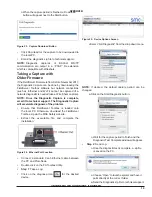
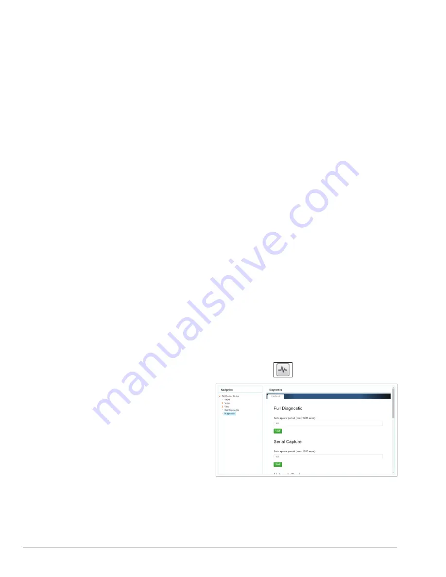
Figure 22.  Full Diagnostics Screen

•  Go to Full Diagnostic and select the capture period.
•  Click  the  Start  button  under  the  Full  Diagnostic 

heading to start the capture.

APPROVED 

UNCONTROLLED DOCUMENT IF PRINTED 


Summary of Contents for FPC-N34: FPC-N35

Page 1: ...TRUCTIONS ProtoNode RER and ProtoNode LER For Interfacing Raypak heating products equipped with the VERSA IC control platform to Building Automation Systems BACnet MS TP BACnet IP Modbus TCP Metasys N2 and LonWorks FPC N34 B 85 FPC N35 B 86 APPROVED UNCONTROLLED DOCUMENT IF PRINTED ...

Page 2: ... of page 4 Figures 1 6 7 9 revised Text revised following Figure 8 Section 4 verbiage and figures revised Figures 14 15 16 19 24 revised Instructions to Upload XIF section revised Appendix A Troubleshooting section revised Appendix B table Point Name descriptions updated APPROVED UNCONTROLLED DOCUMENT IF PRINTED ...

Page 3: ...e ProtoNode RER FPC N34 BACnet or ProtoNode LER FPC N35 LonWorks 12 4 CONNECT TO THE PROTONODE S WEB CONFIGURATOR TO SETUP THE RAYPAK PRODUCTS PROFILES CONNECTED TO THE PROTONODE RER OR LER 12 Connect the PC to the ProtoNode via the Ethernet port 12 Configure Profiles in the ProtoNode s Web Configurator 13 Selecting the Raypak profiles that will be connected the ProtoNode 13 Changing BN_Node_Offse...

Page 4: ...l Raypak products using VERSAIC control platform support ProtoNode Through the ProtoNode Web GUI Configurator the user selects how many VERSA IC Master units are connected to the ProtoNode as well as sets the Modbus Node ID for each VERSA IC Master A Versa IC Master Unit can have up to 169 Modbus points for up to 4 connected Versa IC equipped units Once the Raypak products are selected the ProtoNo...

Page 5: ...orts Figure 1 ProtoNode BACnet RER BACnet and ProtoNode LER LonWorks RER Configuration B 85 BACnet Modbus Metasys To Controller To Controller LER Configuration B 86 LonWorks 2 INTERFACING THE PROTONODE TO RAYPAK PRODUCTS APPROVED UNCONTROLLED DOCUMENT IF PRINTED ...

Page 6: ...figuration for the specific application See Selecting the Raypak profiles that will be connected the ProtoNode on page 13 12 Where the Field protocol is BACnet IP or Modbus TCP run the ProtoNode web GUI utility program to change the IP address No changes to the configuration file are necessary See Set IPAddress for BACnet IP via GUI on page 15 13 Commission the ProtoNode on the LonWorks Network Th...

Page 7: ... S Bank DIP Switch Settings Setting the Device Instance Node ID for BACnet MS TP and BACnet IP on ProtoNode RER FPC N34 BACnet IP BACnet MSTP addressing The BACnet device instances will be set by taking the BN_ Node_Offset found in the Web Configurator See page 13 and added to each Modbus RTU device address set on the Raypak VERSA IC Master units attached to the ProtoNode 50000 is the default If o...

Page 8: ...sure that power to the board is OFF Set Field RS 485 Baud Rate for BACnet MS TP on ProtoNode RER FPC N34 The serial baud rate setting between the BMS and the Protonode has no impact on the communication baud rate between the Versa IC Master and the Protonode The serial baud rate and Versa IC baud rate are not required to match for communication to take place The Versa IC Master baud rate must alwa...

Page 9: ...nnector Connect VERSA IC Modbus pin B RS485 to the ProtoNode s pin 2 RS485 on the Phoenix 6 pin connector Connect VERSA IC Modbus pin GND Ground and the ProtoNode s pin 3 Signal Ground on the Phoenix 6 pin connector Figure 6 VERSA IC Modbus RS485 pin outs to the ProtoNode s Modbus port Raypak Pin ProtoNode Pin Assignment MODBUS A Pin 1 RS 485 MODBUS B Pin 2 RS 485 MODBUS GND Pin 3 RS 485 GND Power...

Page 10: ...ypak VERSA Master Unit 1 Master Unit 2 Raypak VERSA Tx Rx Tx Rx Figure 7 Multiple VERSA IC Masters NOTE Multiple Master configuration requires each Master to have different ID s APPROVED UNCONTROLLED DOCUMENT IF PRINTED ...

Page 11: ... setting from the factory is OFF switch position right side To enable the EOL termination turn the EOL switch ON switch position left side Figure 9 End of line termination on from ProtoNode to RS 485 Field Protocol BACnet MS TP Figure 10 LonWorks Terminal Wiring the ProtoNode LER FPC N35 Field Port to a LonWorks network Connect the ProtoNode to the field network with the LonWorks terminal using a ...

Page 12: ...e PC and ProtoNode The default IP Address for the ProtoNode is 192 168 1 24 Subnet Mask is 255 255 255 0 If the PC and ProtoNode are on different IP networks assign a static IP Address to the PC on the 192 168 1 xxx network For Windows 10 Find the search field in the local computer s taskbar usually to the right of the windows icon and type in Control Panel Power to the ProtoNode ProtoNode Pin Pin...

Page 13: ... will list all the profiles available to select from To add an active profile to the ProtoNode select Add under Active Profiles For every Raypak VERSA IC Master Unit that will be added to the ProtoNode you will need to add the Active Profile on the left of the screen and the Modbus Node Address that the device is assigned to Each Versa IC Master unit must have a unique Modbus Node Address selected...

Page 14: ...nfigurator showing a profile selected Figure 16 Web Configurator showing a completed profile added Continue this process until all the Raypak VERSA IC Master units have been added APPROVED UNCONTROLLED DOCUMENT IF PRINTED ...

Page 15: ...iagnostics and Debugging button at the bottom right corner of the page to go to FSGUI utility Figure 17 Web Configurator showing multiple completed profiles added Click on setup and then Network Settings to enter the Edit IP Address Settings menu Figure 18 ProtoNode Network Settings Tab Type in a new Subnet Mask If necessary change the IP Gateway Default Gateway field Type in a new IP Gateway Note...

Page 16: ...rks assign a static IP Address to the PC on the 192 168 1 xxx network For Windows 10 Find the search field in the local computer s taskbar usually to the right of the windows icon and type in Control Panel Click Control Panel click Network and Internet and then click Network and Sharing Center Click Change adapter settings on the left side of the window Right click on Local Area Connection and sel...

Page 17: ...To request a 2 week complementary BACnet CAS key go to http app chipkin com activation twoweek and fill in all the information Enter Vendor Code Raypak2012 Once completed the key will be sent to the email address that was submitted From this email from Chipkin Automation the long key will need to be copied and pasted into the CAS key activation page Go to Chipkin Automation s web site download and...

Page 18: ...re is a COM issue To fix this check the following o Visual observations of LEDs on ProtoNode Section 8 o Check baud rate parity data bits stop bits o Check device address o Verify wiring o Verify the device was listed in the Web Configurator Section 6 Field COM problems o Visual observations of LEDs on the ProtoNode o Verify IP Address setting o Verify wiring NOTE If the problem persists a Diagnos...

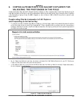
Page 19: ...re will accelerate diagnosis of the problem Ensure that FieldServer Toolbox is loaded onto the local PC Otherwise download the FieldServer Toolbox zip via the MSA Safety website Extract the executable file and complete the installation Figure 24 Ethernet Port Location Connect a standard Cat 5 Ethernet cable between the PC and ProtoNode Double click on the FS Toolbox Utility Step 1 Take a Log Click...

Page 20: ...wer indicating normal operation ERR The SYS ERR LED will go on solid 15 seconds after power up It will turn off after 5 seconds A steady red light will indicate there is a system error on the ProtoNode If this occurs immediately report the related system error shown in the error screen of the GUI interface to FieldServer Technologies for evaluation RX The RX LED will flash when a message is receiv...

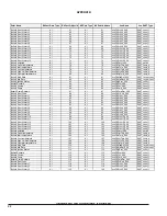
Page 21: ...X SNVT_count_f Boiler1 Error History 1 AI 31 AI 31 nvoLdErHt1_XXX SNVT_count_f Boiler1 Error History 2 AI 32 AI 32 nvoLdErHt2_XXX SNVT_count_f Boiler1 Error History 3 AI 33 AI 33 nvoLdErHt3_XXX SNVT_count_f Boiler1 Error History 4 AI 34 AI 34 nvoLdErHt4_XXX SNVT_count_f Boiler1 Error History 5 AI 35 AI 35 nvoLdErHt5_XXX SNVT_count_f Boiler1 Error History 6 AI 36 AI 36 nvoLdErHt6_XXX SNVT_count_f B...

Page 22: ...y 1 AI 89 AI 89 nvoFl2ErHt1_XXX SNVT_count_f Boiler3 Error History 2 AI 90 AI 90 nvoFl2ErHt2_XXX SNVT_count_f Boiler3 Error History 3 AI 91 AI 91 nvoFl2ErHt3_XXX SNVT_count_f Boiler3 Error History 4 AI 92 AI 92 nvoFl2ErHt4_XXX SNVT_count_f Boiler3 Error History 5 AI 93 AI 93 nvoFl2ErHt5_XXX SNVT_count_f Boiler3 Error History 6 AI 94 AI 94 nvoFl2ErHt6_XXX SNVT_count_f Boiler3 Error History 7 AI 95 ...

Page 23: ...viDHWDiff_XXX SNVT_temp_p DHW Priority BV 144 DO 144 nviDHWPrio_XXX SNVT_switch DHW During UnOcc BV 145 DO 145 nviDHWUnOc_XXX SNVT_switch WWSD During Occ AV 146 AO 146 nviWWSDOcc_XXX SNVT_temp_p WWSD During UnOcc AV 147 AO 147 nviWWSDUnOc_XXX SNVT_temp_p Tank Setpoint AV 148 AO 148 nviTnkSP_XXX SNVT_temp_p Tank Differential AV 149 AO 149 nviTnkDiff_XXX SNVT_temp_p Tank During UnOcc BV 150 DO 150 n...

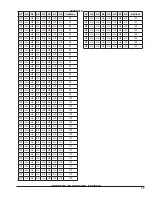
Page 24: ...f On Off Off 36 Off Off On Off Off On Off On 37 Off Off On Off Off On On Off 38 A7 A6 A5 A4 A3 A2 A1 A0 Address Off Off On Off Off On On On 39 Off Off On Off On Off Off Off 40 Off Off On Off On Off Off On 41 Off Off On Off On Off On Off 42 Off Off On Off On Off On On 43 Off Off On Off On On Off Off 44 Off Off On Off On On Off On 45 Off Off On Off On On On Off 46 Off Off On Off On On On On 47 Off O...

Page 25: ... 101 Off On On Off Off On On Off 102 Off On On Off Off On On On 103 Off On On Off On Off Off Off 104 Off On On Off On Off Off On 105 Off On On Off On Off On Off 106 Off On On Off On Off On On 107 Off On On Off On On Off Off 108 Off On On Off On On Off On 109 Off On On Off On On On Off 110 Off On On Off On On On On 111 Off On On On Off Off Off Off 112 Off On On On Off Off Off On 113 Off On On On Of...

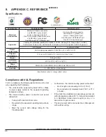
Page 26: ...evice must not be connected to a LAN segment with outdoor wiring Specification ProtoNode RER ProtoNode LER Electrical Connections One 6 pin Phoenix connector one RS 485 ground port power frame ground port One 3 pin RS 485 Phoenix connector one RS 485 ground port One Ethernet 10 100 Ethernet port One 6 pin Phoenix connector one RS 485 ground port power frame ground port One Ethernet 10 100 BaseT po...

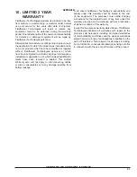
Page 27: ...ave been removed or altered This Limited Warranty also will not apply to interconnecting cables or wires consumables or to any damage resulting from battery leakage In all cases FieldServer Technology s responsibility and liability under this warranty shall be limited to the cost of the equipment The purchaser must obtain shipping instructions for the prepaid return of any item under this warranty...

Page 28: ...28 Raypak Inc 2151 Eastman Avenue Oxnard CA 93030 805 278 5300 Fax 805 278 5468 NOTES APPROVED UNCONTROLLED DOCUMENT IF PRINTED ...

Reviews: