________________________________________________________________________________________________________________
12-20-2002
Figure Sheet 1-853-A
Page 17
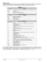
SBPC-21-EN/IP Data Flow
In order to effectively connect two dissimilar networks, some means must be provided to collect the
data from each network and exchange it in a controlled manner so that no partial or incomplete data is
sent on either network. This is accomplished by using a block of memory in the SBPC-21-EN/IP to
reassemble FifeNet time slice data and then when it is complete, transfer it to the EtherNet/IP buffers
for transmission on EtherNet/IP. Keep in mind that the gateway has to be bidirectional so this process
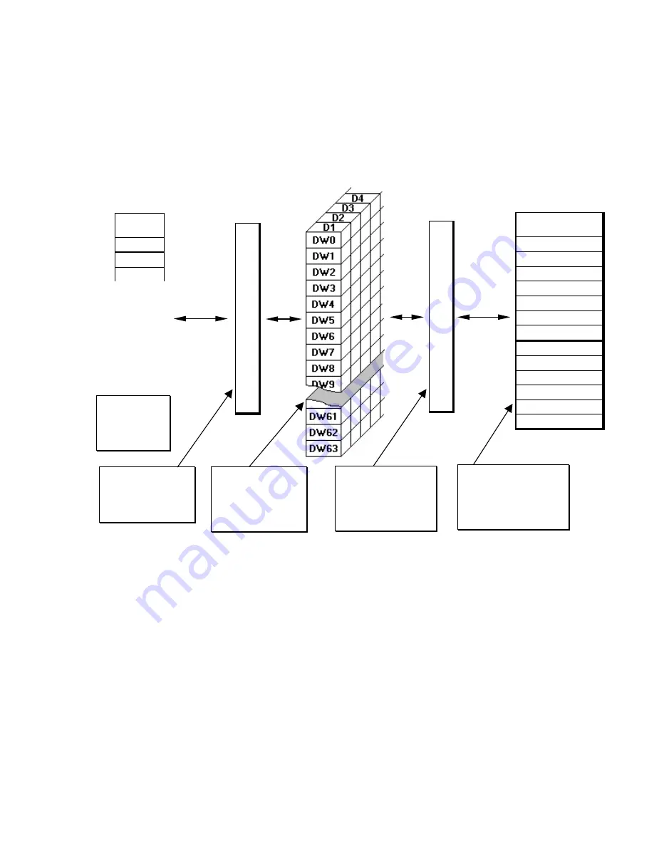
works the same way for data traveling from EtherNet/IP to FifeNet. The diagram below shows the
process.
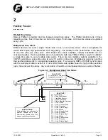
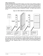
Figure 2-2: SBPC-21-EN/IP Data Flow Block Diagram
As you can see in Figure 2-2, each time slice has enough memory to store 64 16-bit data words. This
is the maximum amount of data that appears on a FifeNet multiplexed time slice. These data words
are referenced by their order of reception in the multiplexed sequence with DW0 being first and DW63
being last. When the time slice is used in the real-time mode, only the first location DW0 in the
memory array is used. Multiplexed modes 4, 8, and 16 each use 4, 8, and 16 words of memory,
respectively.
The time slice
buffers hold
the raw time
slice data.
EtherNet data is placed
here for transmission.
Consumed data is read
from here and sent to
FifeNet.
This matrix is used to
connect EtherNet
scheduled data to
any memory buffer
location.
The memory array
is used to assemble
and hold data
passing through the
gateway.
This matrix is used
to connect any time
slice to any memory
buffer location.
M
A
T
R
I
X
M
A
T
R
I
X
EtherNet/IP Data
FifeNet
D1
D2
D3
•
•
•
•
•
•
•
•

